GD32F3x0 User Manual
277
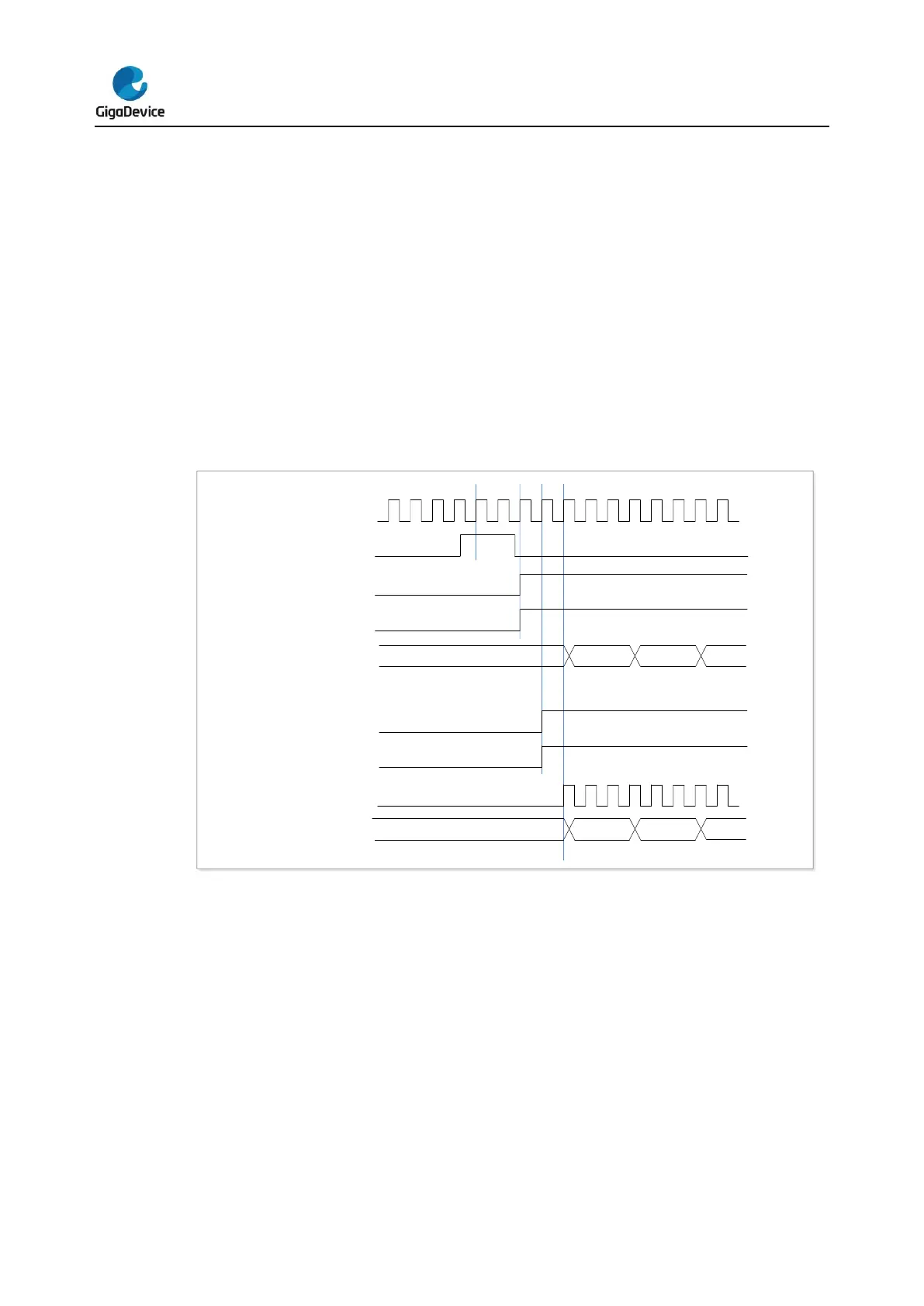
triggered by its CI0 input rises edge. To ensure 2 timers start synchronously, TIMER1 must
be configured in Master/Slave mode. Do as follow:
1. Configure TIMER1 slave mode to get the input trigger from CI0 (TRGS=100 in the
TIMER1_SMCFG register).
2. Configure TIMER1 in event mode (SMC=110 in the TIMER1_SMCFG register).
3. Configure the TIMER1 in Master/Slave mode by writing MSM=1 (TIMER1_SMCFG
register).
4. Configure TIMER0 to get the input trigger from TIMER1 (TRGS=001 in the
TIMER0_SMCFG register).
5. Configure TIMER0 in event mode (SMC=110 in the TIMER1_SMCFG register).
When a rising edge occurs on TIMER1’s CI0, two timer counters starts counting
synchronously on the internal clock and both TRGIF flags are set.
Figure 16-28. Triggering TIMER0 and TIMER1 with TIMER1’s CI0 input
Timer DMA mode
Timer’s DMA mode is the function that configures timer’s register by DMA module. The
relative registers are TIMERx_DMACFG and TIMERx_DMATB. Of course, you have to
enable a DMA request which will be asserted by some internal event. When the interrupt
event was asserted, TIMERx will send a request to DMA, which is configured to M2P mode
and PADDR is TIMERx_DMATB, then DMA will access the TIMERx_DMATB. In fact, register
TIMERx_DMATB is only a buffer; timer will map the TIMERx_DMATB to an internal register,
appointed by the field of DMATA in TIMERx_DMACFG. If the field of DMATC in
TIMERx_DMACFG is 0(1 transfer), then the timer’s DMA request is finished. While if
TIMERx_DMATC is not 0, such as 3(4 transfers), then timer will send 3 more requests to
DMA, and DMA will access timer’s registers DMATA+0x4, DMATA+0x8, DMATA+0xc at the


 To Next Page