EasyManua.ls Logo

GigaDevice Semiconductor GD32F3x0 - Figure 16-21. Hall Sensor Timing between Two Timers; Table 16-4. Slave Mode Example Table

Default Icon
665 pages
Print Icon
To Next Page IconTo Next Page
To Previous Page IconTo Previous Page
Loading...
GD32F3x0 User Manual
272
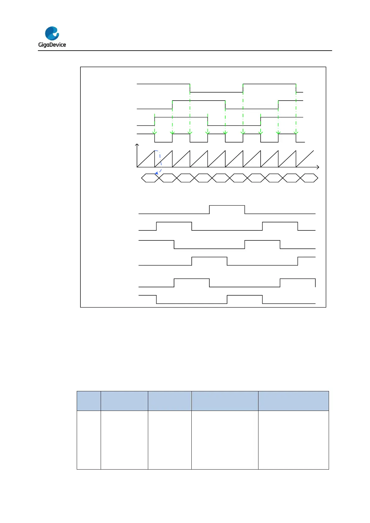
Figure 16-21. Hall sensor timing between two timers
CH0VAL
Counter
CI0(OXR)
CH0_IN
CH1_IN
CH2_IN
CH0_O
CH0_ON
CH1_O
CH1_ON
CH2_O
CH2_ON
Va
Va
Vb
Vb
Vc
Vc
Advanced/General L0 TIMER_in under input capture mode
Advanced TIMER_out under output compare mode(PWM with Dead-time)
Master-slave management
The TIMERx can be synchronized with a trigger in several modes including the restart mode,
the pause mode and the event mode which is selected by the SMC [2:0] in the
TIMERx_SMCFG register. The trigger input of these modes can be selected by the TRGS
[2:0] in the TIMERx_SMCFG register.
Table 16-4. Slave mode example table
Mode Selection
Source
Selection
Polarity Selection
Filter and Prescaler
LIST
SMC[2:0]
3'b100 (restart
mode)
3'b101 (pause
mode)
3'b110 (event
TRGS[2:0]
000: ITI0
001: ITI1
010: ITI2
011: ITI3
100: CI0F_ED
If you choose the CI0FE0
or CI1FE1, configure the
CHxP and CHxNP for the
polarity selection and
inversion.
If you choose the ETIF,
For the ITIx no filter and
prescaler can be used.
For the CIx, configure Filter
by CHxCAPFLT, no
prescaler can be used.
For the ETIF, configure

Table of Contents