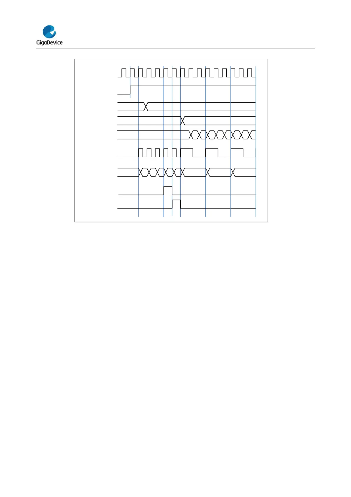
Counter up counting
In this mode, the counter counts up continuously from 0 to the counter-reload value, which is
defined in the TIMERx_CAR register, in a count-up direction. Once the counter reaches the
counter reload value, the counter will start counting up from 0 again. The update event is
generated at each counter overflow. The counting direction bit DIR in the TIMERx_CTL1
register should be set to 0 for the up counting mode.
When the update event is set by the UPG bit in the TIMERx_SWEVG register, the counter
value will be initialized to 0 and generates an update event.
If the UPDIS bit in TIMERx_CTL0 register is set, the update event is disabled.
When an update event occurs, all the shadow registers (counter auto reload register,
prescaler register) are updated.
The following figures show some examples of the counter behavior for different clock
prescaler factor when TIMERx_CAR=0x99.


 To Next Page