GD32F3x0 User Manual
352
Input capture and output compare channels
The general level2 timer has one independent channel which can be used as capture inputs
or compare match outputs. Each channel is built around a channel capture compare register
including an input stage, channel controller and an output stage.
Channel input capture function
Channel input capture function allows the channel to perform measurements such as pulse
timing, frequency, period, duty cycle and so on. The input stage consists of a digital filter, a
channel polarity selection, edge detection and a channel prescaler. When a selected edge
occurs on the channel input, the current value of the counter is captured into the
TIMERx_CHxCV register, at the same time the CHxIF bit is set and the channel interrupt is
generated if enabled by CHxIE = 1.
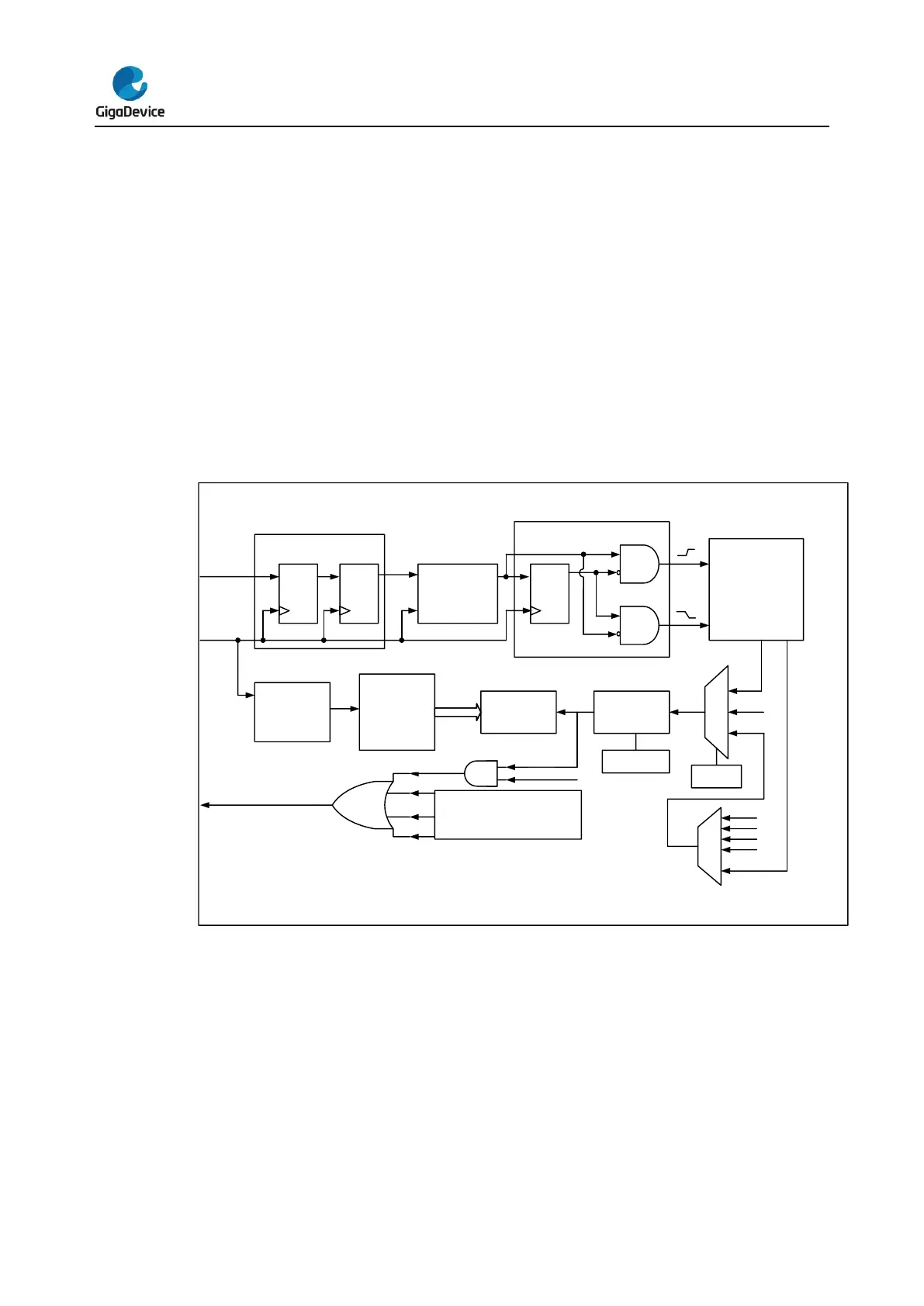
Figure 16-50. Channel input capture principle
First, the channel input signal (CIx) is synchronized to TIMER_CK domain, and then
sampled by a digital filter to generate a filtered input signal. Then through the edge detector,
the rising and fall edge are detected. You can select one of them by CHxP. One more
selector is for the other channel and trig, controlled by CHxMS. The IC_prescaler make
several the input event generate one effective capture event. On the capture event, CHxVAL
will restore the value of Counter.
So, the process can be divided to several steps as below:
Step1: Filter configuration. (CHxCAPFLT in TIMERx_CHCTL0)
Based on the input signal and requested signal quality, configure compatible