GD32F3x0 User Manual
310
When the update event is set by the UPG bit in the TIMERx_SWEVG register, the counter
value will be initialized to 0 and generates an update event.
If the UPDIS bit in TIMERx_CTL0 register is set, the update event is disabled.
When an update event occurs, all the shadow registers (counter auto reload register,
prescaler register) are updated.
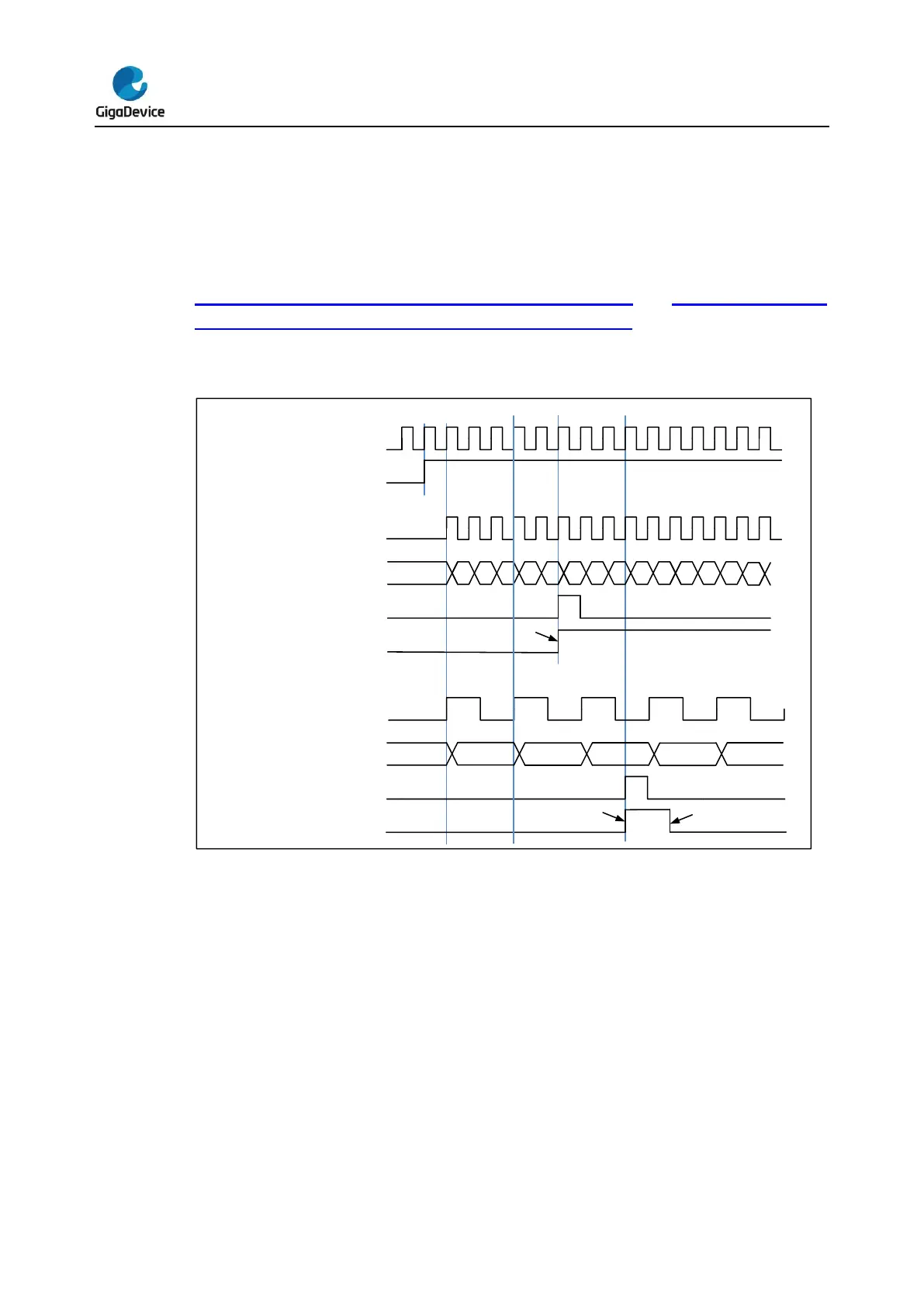
Figure 16-32. Timing chart of up counting mode, PSC=0/2 and Figure 16-33. Timing
chart of up counting mode, change TIMERx_CAR on the go. show some examples of the
counter behavior for different clock prescaler factor when TIMERx_CAR=0x99.
Figure 16-32. Timing chart of up counting mode, PSC=0/2