GD32F3x0 User Manual
487
to the following command on I2C bus: transmitting or receiving the desired data. Additionally,
if General Call is enabled by software, the I2C slave always responds to a General Call
Address (0x00). The I2C block supports both 7-bit and 10-bit address modes.
An I2C master always initiates or ends a transfer using START or STOP signal and it’s also
responsible for SCL clock generation.
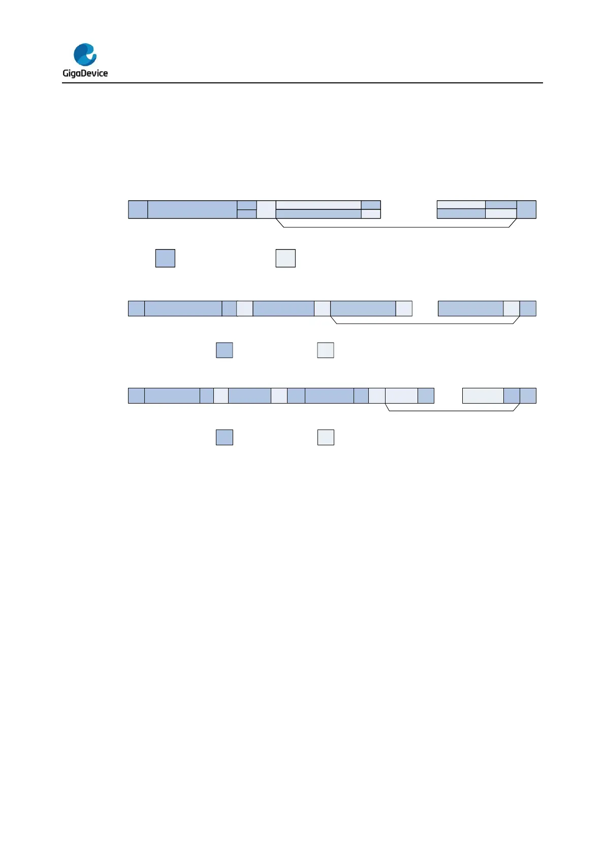
Figure 19-6. I2C communication flow with 7-bit address
Start Slave address
W(0)
ACK
DATA0 ACK
DATAN
ACK
Stop
data transfer (N+1 bytes)
From master to slave From slave to master
R(1)
DATA0
ACK
DATAN
NACK
Figure 19-7. I2C communication flow with 10-bit address (Master Transmit)
Start Slave address byte2
W(0)
ACK DATA0 ACK DATAN
ACK
Stop
data transfer (N+1 bytes)
From master to slave From slave to master
Slave address byte1
(header)
ACK
1 1 1 1 0 x x
Figure 19-8. I2C communication flow with 10-bit address (Master Receive)
Start
Slave address
byte2
W(0)
ACK DATA0 ACK DATAN
NACK
Stop
data transfer (N+1 bytes)
From master to slave From slave to master
Slave address byte1
(header)
ACK
1 1 1 1 0 x x
ACK
Slave address
byte1 (header)
Start
R(1)
19.3.7. Programming model
An I2C device such as LCD driver may only be a receiver, whereas a memory can both
receive and transmit data. In addition to transmitters and receivers, devices can also be
considered as masters or slaves when performing data transfers. A master is the device
which initiates a data transfer on the bus and generates the clock signals to permit that
transfer. At that time, any device addressed is considered as a slave.
An I2C device is able to transmit or receive data whether it’s a master or a slave, thus,
there’re 4 operation modes for an I2C device:
Master Transmitter
Master Receiver
Slave Transmitter
Slave Receiver
I2C block supports all of the four I2C modes. After system reset, it works in slave mode. After
sending a START signal on I2C bus, it changes into master mode. The I2C changes back to
slave mode after sending a STOP signal on I2C bus.