Single pulse mode
Single pulse mode is opposite to the repetitive mode, which can be enabled by setting SPM
in TIMERx_CTL0. When you set SPM, the counter will be clear and stop when the next
update event. In order to get pulse waveform, you can set the TIMERx to PWM mode or
compare by CHxCOMCTL.
Once the timer is set to operate in the single pulse mode, it is not necessary to set the timer
enable bit CEN in the TIMERx_CTL0 register to 1 to enable the counter. The trigger to
generate a pulse can be sourced from the trigger signals edge or by setting the CEN bit to 1
using software. Setting the CEN bit to 1 or a trigger from the trigger signals edge can
generate a pulse and then keep the CEN bit at a high state until the update event occurs or
the CEN bit is written to 0 by software. If the CEN bit is cleared to 0 using software, the
counter will be stopped and its value held.
In the single pulse mode, the trigger active edge which sets the CEN bit to 1 will enable the
counter. However, there exist several clock delays to perform the comparison result between
the counter value and the TIMERx_CHxCV value. In order to reduce the delay to a minimum
value, the user can set the CHxCOMFEN bit in each TIMERx_CHCTL0/1 register. After a
trigger rising occurs in the single pulse mode, the OxCPRE signal will immediately be forced
to the state which the OxCPRE signal will change to, as the compare match event occurs
without taking the comparison result into account. The CHxCOMFEN bit is available only
when the output channel is configured to operate in the PWM0 or PWM1 output mode and
the trigger source is derived from the trigger signal.
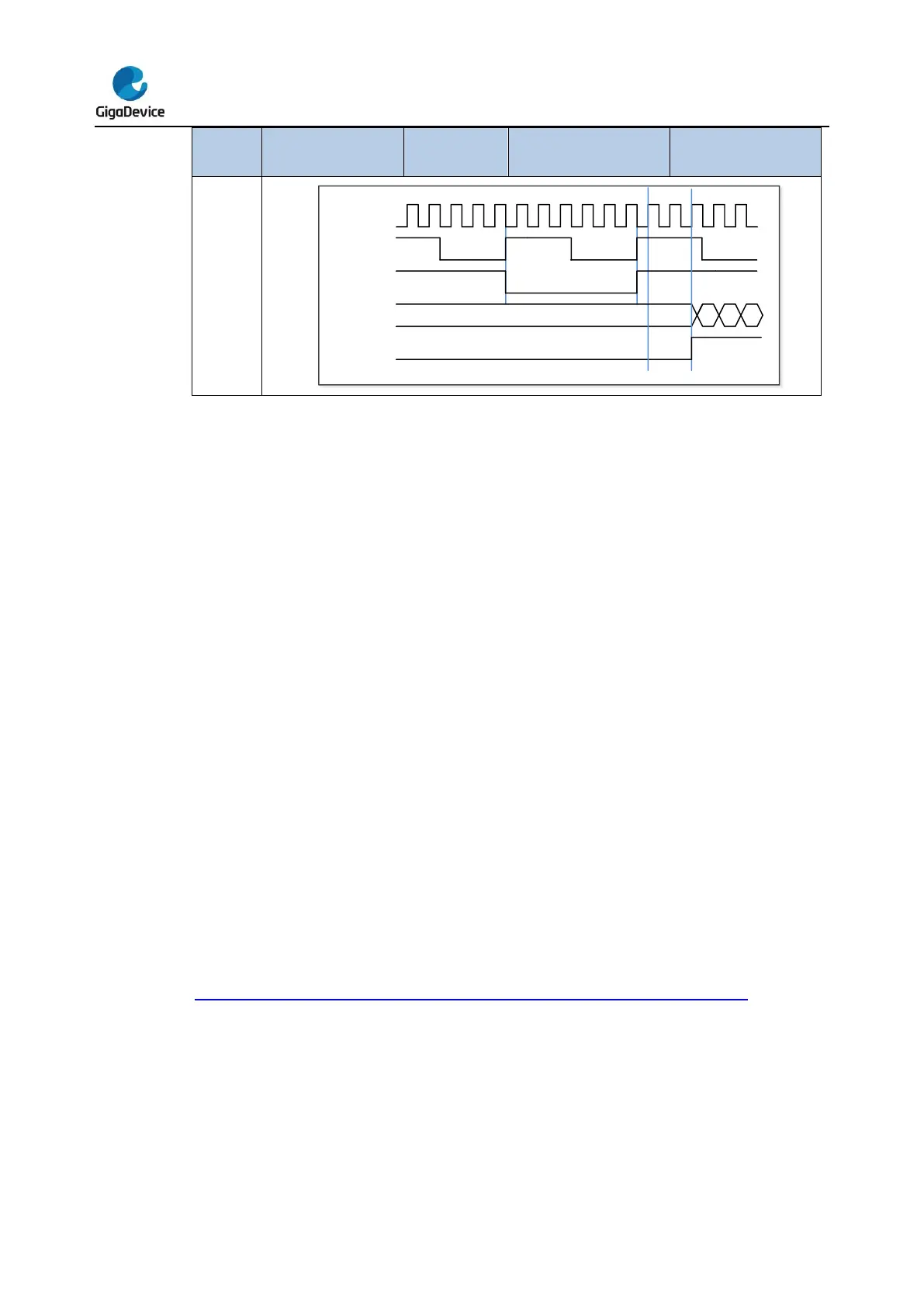
Figure 16-44. Single pulse mode TIMERx_CHxCV = 4 TIMERx_CAR=99 shows an
example.