This FSM remains in IDLE state after reset. There are 2 kinds of start condition defined by
TRGMOD bit in TSI_CTL0 register:
TRGMOD = 0: Software Trigger Mode. In this mode, the FSM starts after TSIS bit in
TSI_CTL0 register is written 1 by software.
TRGMOD = 1: Hardware Trigger Mode. In this mode the FSM starts when a falling or rising
edge on TSITG pin is detected.
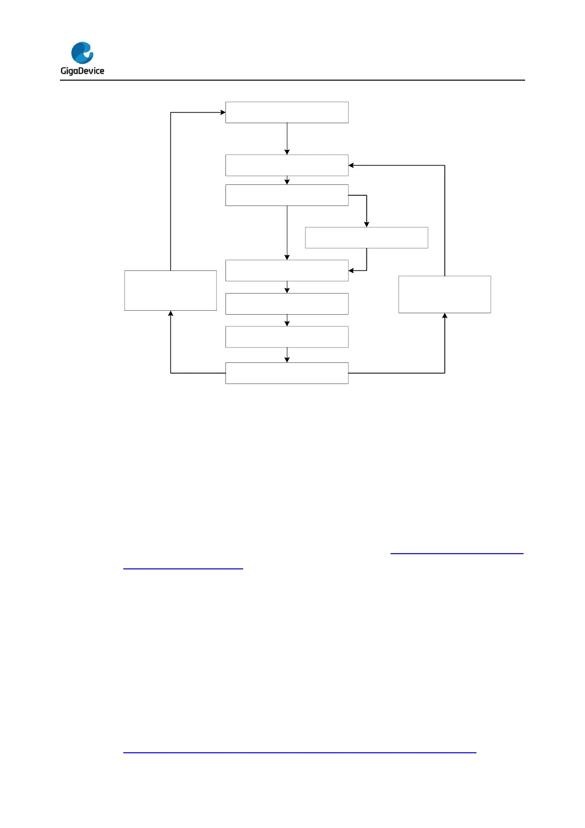
Once started, the FSM runs following the flow described in Figure 22-4. FSM flow of a
charge-transfer sequence. The FSM leaves a state if the duration time of this state reaches
defined value, and goes into the next state.
The Extend Charge state is present only if the ECEN bit is set in TSI_CTL0 register. This
state is designed to implement spread spectrum function, which will extend the duration of
the pulse high state with different extend time according to current FSM cycle number. So in
other word, the charge frequency becomes dynamic and not fixed. In case of noisy
application environment, enabling this function can improve the robustness of TSI. At the
same time, system’s electromagnetic emissions will be reduced.
In comparing state, the FSM compares voltage of the sample pin in every enabled group and
the threshold voltage. If all sample pins’ voltage reach the threshold, FSM returns IDLE state
and stops, otherwise, it returns to Buffer Time 1 state and begins the next cycle. As shown in
Figure 22-3. Voltage of a sample pin during charge-transfer sequence,after 27


 To Next Page