The TIMERx_TRGO signals are generated from the timers, while the software trigger can be
generated by setting the SWTR bit in the DAC_SWT register.
12.3.5. DAC workflow
If the external trigger enabled by setting the DTEN bit in DAC_CTL register, the DAC holding
data is transferred to the DAC output data (DAC_DO) register when the selected trigger
events. When the external trigger is disabled, the transfer is performed automatically.
When the DAC holding data (DAC_DH) is loaded into the DAC_DO register, after the time
t
SETTLING
, the analog output is valid, and the value of t
SETTLING
is related to the power supply
voltage and the analog output load.
12.3.6. DAC noise wave
There are two methods of adding noise wave to the DAC output data: LFSR noise wave
mode and triangle wave mode. The noise wave mode can be selected by the DWM bits in
the DAC_CTL register. The amplitude of the noise can be configured by the DAC noise wave
bit width (DWBW) bits in the DAC_CTL register.
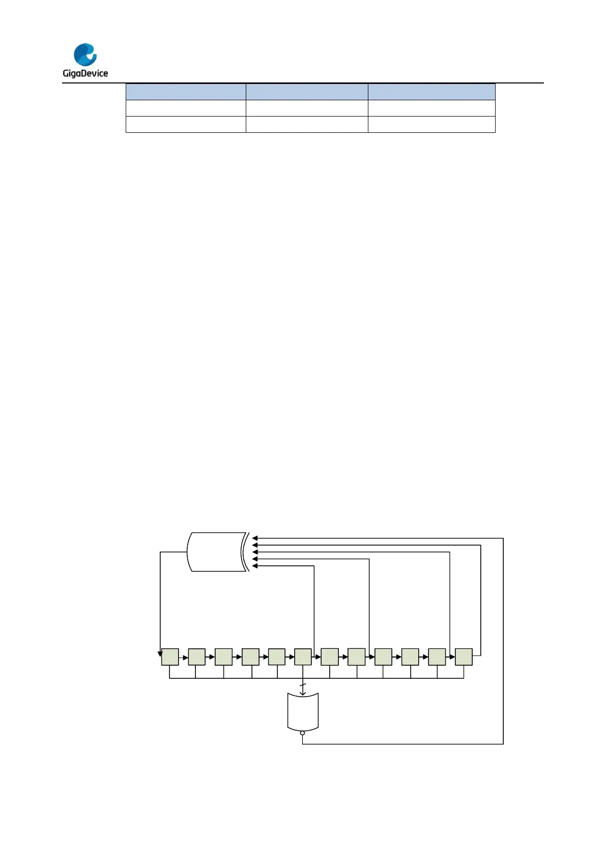
LFSR noise wave mode: there is a Linear Feedback Shift Register (LFSR) in the DAC
control logic, it controls the LFSR noise signal which is added to the DACx_DH value. When
the configured DAC noise wave bit width is less than 12, the noise signal equals to the LSB
DWBWx bits of the LFSR register, while the MSB bits are masked.
Figure 12-2. DAC LFSR algorithm
 Loading...

