TIMER_CK
CEN
PSC_CLK
CNT_REG
94 95 96 97 98 99
0 1 2 3 4
5 6 7
Update event (UPE)
Update interrupt flag (UPIF)
Auto-reload register
120
99
change CAR Vaule
CNT_REG
113 114 115 116 117 118
119 120 0 1 2
98 99 0
Update event (UPE)
Update interrupt flag (UPIF)
Auto-reload register
120
99
change CAR Vaule
120 99
Auto-reload shadow register
...
Hardware set
Hardware set
Software clear
Hardware set
ARSE = 0
ARSE = 1
Counter down counting
In this mode, the counter counts down continuously from the counter-reload value, which is
defined in the TIMERx_CAR register, to 0 in a count-down direction. Once the counter
reaches to 0, the counter the counter will start counting down from the counter-reload value
again and an underflow event will be generated. In addition, the update event will be
generated after (TIMERx_CREP+1) times of underflow. The counting direction bit DIR in the
TIMERx_CTL0 register should be set to 1 for the down-counting mode.
When the update event is set by the UPG bit in the TIMERx_SWEVG register, the counter
value will be initialized to the counter-reload value and generates an update event.
If set the UPDIS bit in TIMERx_CTL0 register, the update event is disabled.
When an update event occurs, all the shadow registers (repetition counter, counter auto
reload register, prescaler register) are updated.
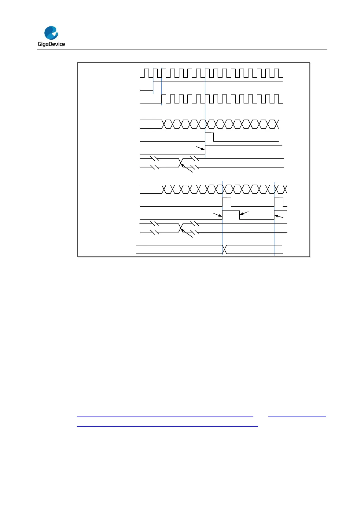
Figure 16-6. Timing chart of down counting mode, PSC=0/2 and Figure 16-7. Timing
chart of down counting mode, change TIMERx_CAR on the go show some examples of
the counter behavior in different clock frequencies when TIMERx_CAR=0x99.
 Loading...

