7.3.5. Output configuration
When GPIO pin is configured as output:
The schmitt trigger input is activated.
The weak pull-up and pull-down resistors could be chosen.
The output buffer is enabled:
– Open-Drain mode: The pad outputs “0” when a “0” in the output control register;
while the pad leaves Hi-Z when a “1” in the output control register.
– Push-Pull mode: The pad outputs “0” when a “0” in the output control register; while
the pad outputs “1” when a “1” in the output control register.
A read access to the port output control register gets the last written value in Push-Pull
mode
A read access to the port input status register gets the I/O state in Open-Drain mode
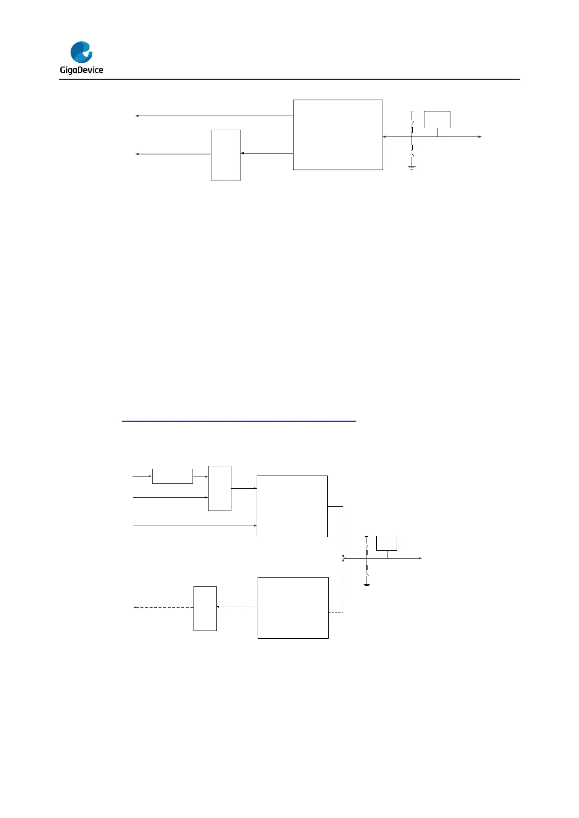
Figure 7-3. Basic structure of Output configuration shows the output configuration of the
GPIO pin.
Figure 7-3. Basic structure of Output configuration
7.3.6. Analog configuration
When GPIO pin is used as analog configuration:
The weak pull-up and pull-down resistors are disabled.
The output buffer is disabled.


 To Next Page