EasyManua.ls Logo

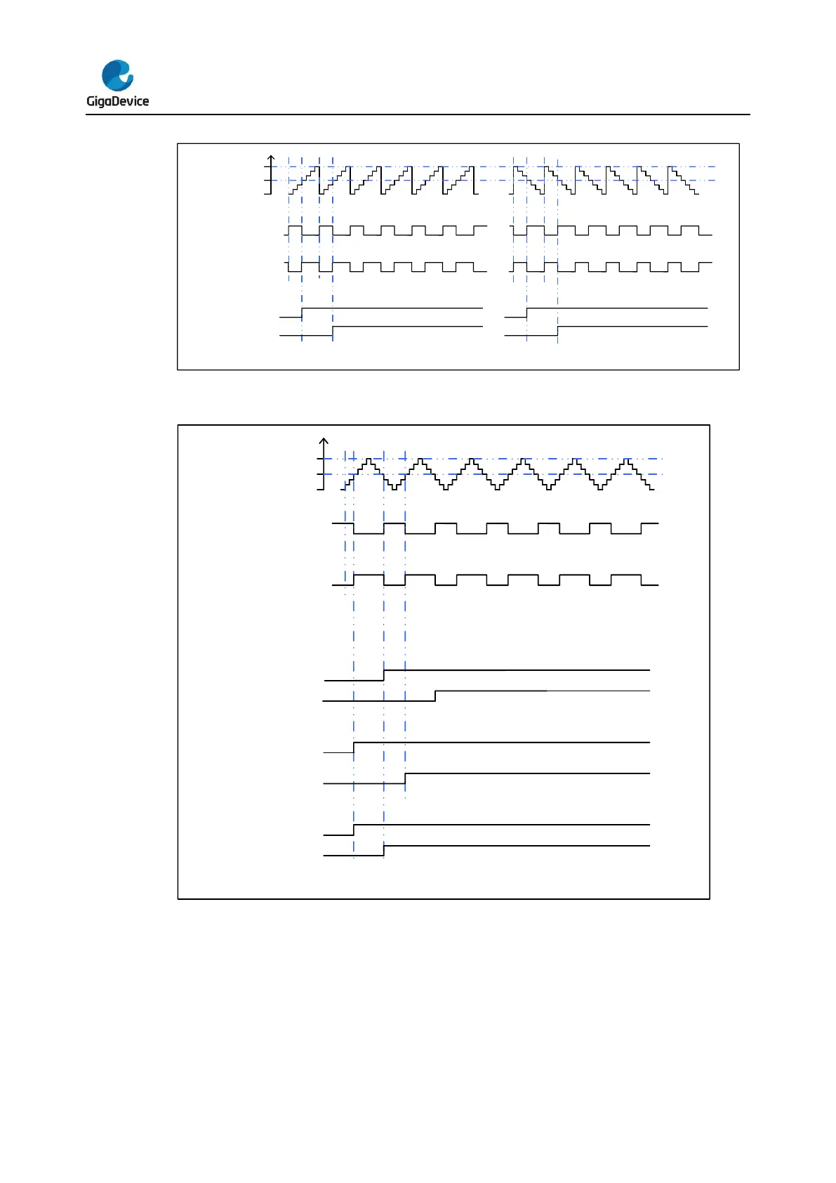
GigaDevice Semiconductor GD32F3x0 - Figure 16-14. EAPWM Timechart; Figure 16-15. CAPWM Timechart

Default Icon
665 pages
Print Icon
To Next Page IconTo Next Page
To Previous Page IconTo Previous Page
Loading...
GD32F3x0 User Manual
265
Figure 16-14. EAPWM timechart
0
CHxVAL
CAR
PWM MODE0
PWM MODE1
Cx OUT
Cx OUT
Interrupt signal
CHxIF
CHxOF
Figure 16-15. CAPWM timechart
0
CHxVAL
CAR
PWM MODE0
Cx OUT
PWM MODE1
Cx OUT
Interrupt signal
CHxIF
CHxOF
CAM=2'b01 down only
CAM=2'b10 up only
CHxIF
CHxOF
CAM=2'b11 up/down
CHxIF
CHxOF
Channel output prepare signal
When the TIMERx is used in the compare match output mode, the OxCPRE signal (Channel
x Output prepare signal) is defined by setting the CHxCOMCTL filed. The OxCPRE signal
has several types of output function. These include, keeping the original level by setting the
CHxCOMCTL field to 0x00, set to 1 by setting the CHxCOMCTL field to 0x01, set to 0 by
setting the CHxCOMCTL field to 0x02 or signal toggle by setting the CHxCOMCTL field to

Table of Contents