Timer DMA mode
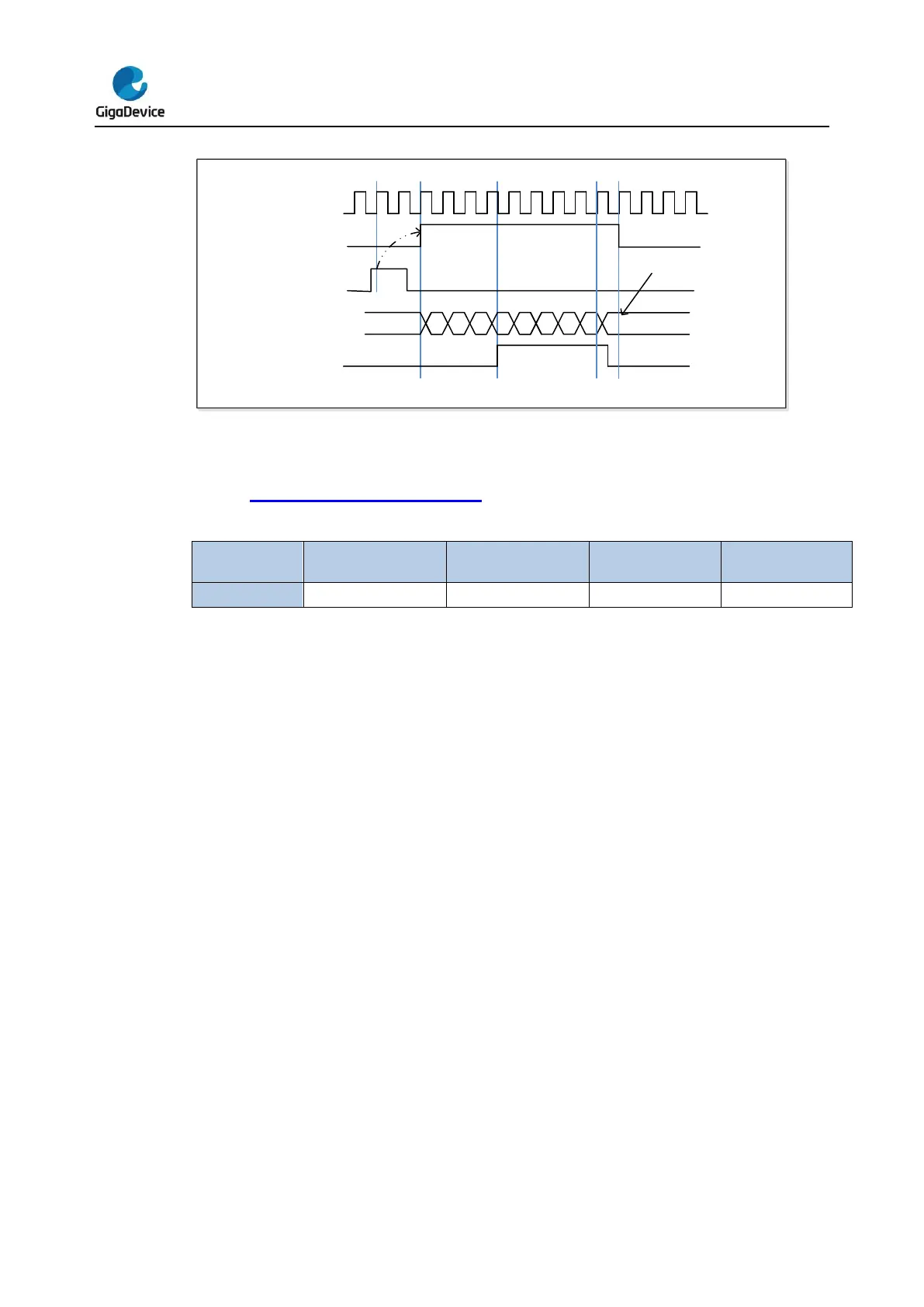
Timer’s DMA mode is the function that configures timer’s register by DMA module. The
relative registers are TIMERx_DMACFG and TIMERx_DMATB. Of course, you have to
enable a DMA request which will be asserted by some internal event. When the interrupt
event was asserted, TIMERx will send a request to DMA, which is configured to M2P mode
and PADDR is TIMERx_DMATB, then DMA will access the TIMERx_DMATB. In fact, register
TIMERx_DMATB is only a buffer; timer will map the TIMERx_DMATB to an internal register,
appointed by the field of DMATA in TIMERx_DMACFG. If the field of DMATC in
TIMERx_DMACFG is 0(1 transfer), then the timer’s DMA request is finished. While if
TIMERx_DMATC is not 0, such as 3(4 transfers), then timer will send 3 more requests to
DMA, and DMA will access timer’s registers DMATA+0x4, DMATA+0x8, DMATA+0xc at the
next 3 accesses to TIMERx_DMATB. In a word, one-time DMA internal interrupt event assert,
DMATC+1 times request will be send by TIMERx.
If one more time DMA request event coming, TIMERx will repeat the process as above.
Timer debug mode
When the Cortex
®
-M4 halted, and the TIMERx_HOLD configuration bit in DBG_CTL1
register set to 1, the TIMERx counter stops.


 To Next Page