High
Impedence
Low Impedence
Ts
Logic
0
Logic
1
1.5ms 2.4ms
T1
0.6ms
T2 T5
T3 T4 T6 T7 T8
2.4ms
Legend:
Checking Window
BRE
BRE
SBPE
Nominal sample time 1.05 ms
LBPE
High
Impedence
Low Impedence
Table 21-2. Error Handling Timing Parameter Table
When indicating a logical 1, T1 as the earliest time for a low -
high transition.
When indicating a logical 1, T2 as the latest time for a low - high
transition.
The earliest time it is safe to sample the signal line to determine
its state.
The latest time it is safe to sample the signal line to determine
its state.
T5 as the earliest time that a device is allowed to return to a high
impedance state(logical 0).
T6 as the latest time that a device is allowed to return to a high
impedance state(logical 0).
T7 as the earliest time for the start of a following bit.
As a nominal data bit period.
T8 as the latest time for the start of a following bit.
Transmission error detection(TERR)
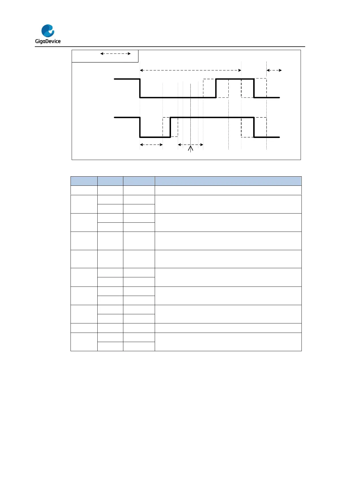
The TERR is set when the initiator find low impedance on the CEC bus when it is
transmitting high impedance. TERR will also generate CEC interrupt if TERRIE=1.
When TERR asserted the transmission is aborted and the software can retry the
transmission.
TERR check window is depending on the different bit state of the frame shown as below:
Figure 21-7. Transmission error detection


 To Next Page