GD32F3x0 User Manual
253
16.1.4. Function overview
Clock source configuration
The advanced timer has the capability of being clocked by either the CK_TIMER or an
alternate clock source controlled by SMC (TIMERx_SMCFG bit [2:0]).
SMC [2:0] == 3’b000. Internal clock CK_TIMER is selected as timer clock source which
is from module RCU.
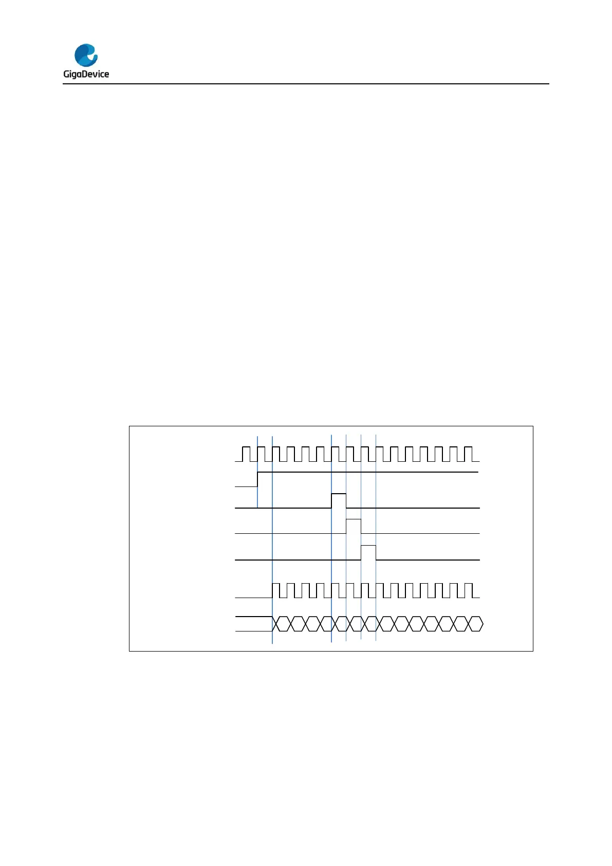
The default clock source is the CK_TIMER for driving the counter prescaler when the SMC
[2:0] = 3’b000. When the CEN is set, the CK_TIMER will be divided by PSC value to
generate PSC_CLK.
In this mode, the TIMER_CK, which drives counter’s prescaler to count, is equal to
CK_TIMER which is from RCU.
If the SMC [2:0] in the TIMERx_SMCFG register are setting to an available value including
0x1, 0x2, 0x3 and 0x7, the prescaler is clocked by other clock sources selected by the TRGS
[2:0] in the TIMERx_SMCFG register, details as follows. When the SMC [2:0] bits are set to
0x4, 0x5 or 0x6, the internal clock CK_TIMER is the counter prescaler driving clock source.
Figure 16-2. Timing chart of internal clock divided by 1
SMC [2:0] == 3’b111 (external clock mode 0). External input pin is selected as timer
clock source
The TIMER_CK, which drives counter’s prescaler to count, can be triggered by the event of
rising or falling edge on the external pin TIMERx_CH0/TIMERx_CH1. This mode can be
selected by setting SMC [2:0] to 0x7 and the TRGS [2:0] to 0x4, 0x5 or 0x6.
And, the counter prescaler can also be driven by rising edge on the internal trigger input pin
 Loading...

