GD32F3x0 User Manual
528
20.4.2. I2S signal description
There are four pins on the I2S interface, including I2S_CK, I2S_WS, I2S_SD and I2S_MCK.
I2S_CK is the serial clock signal, which shares the same pin with SPI_SCK. I2S_WS is the
frame control signal, which shares the same pin with SPI_NSS. I2S_SD is the serial data
signal, which shares the same pin with SPI_MOSI. I2S_MCK is the master clock signal. It
produces a frequency rate equal to 256 x Fs, and Fs is the audio sampling frequency.
20.4.3. I2S audio standards
The I2S audio standard is selected by the I2SSTD bits in the SPI_I2SCTL register. Four
audio standards are supported, including I2S Phillips standard, MSB justified standard, LSB
justified standard, and PCM standard. All standards except PCM handle audio data
time-multiplexed on two channels (the left channel and the right channel). For these
standards, the I2S_WS signal indicates the channel side. For PCM standard, the I2S_WS
signal indicates frame synchronization information.
The data length and the channel length are configured by the DTLEN bit and CHLEN bit in
the SPI_I2SCTL register. Since the channel length must be greater than or equal to the data
length, four packet types are available. They are 16-bit data packed in 16-bit frame, 16-bit
data packed in 32-bit frame, 24-bit data packed in 32-bit frame, and 32-bit data packed in
32-bit frame. The data buffer for transmission and reception is 16-bit wide. In the case that
the data length is 24 bits or 32 bits, two write or read operations to or from the SPI_DATA
register are needed to complete the transmission of a frame. In the case that the data length
is 16-bit, only one write or read operation to or from the SPI_DATA register is needed to
complete the transmission of a frame. When using 16-bit data packed in 32-bit frame, 16-bit
0 is inserted by hardware automatically to extend the data to 32-bit format.
For all standards and packet types, the most significant bit (MSB) is always sent first. For all
standards based on two channels time-multiplexed, the channel left is always sent first
followed by the channel right.
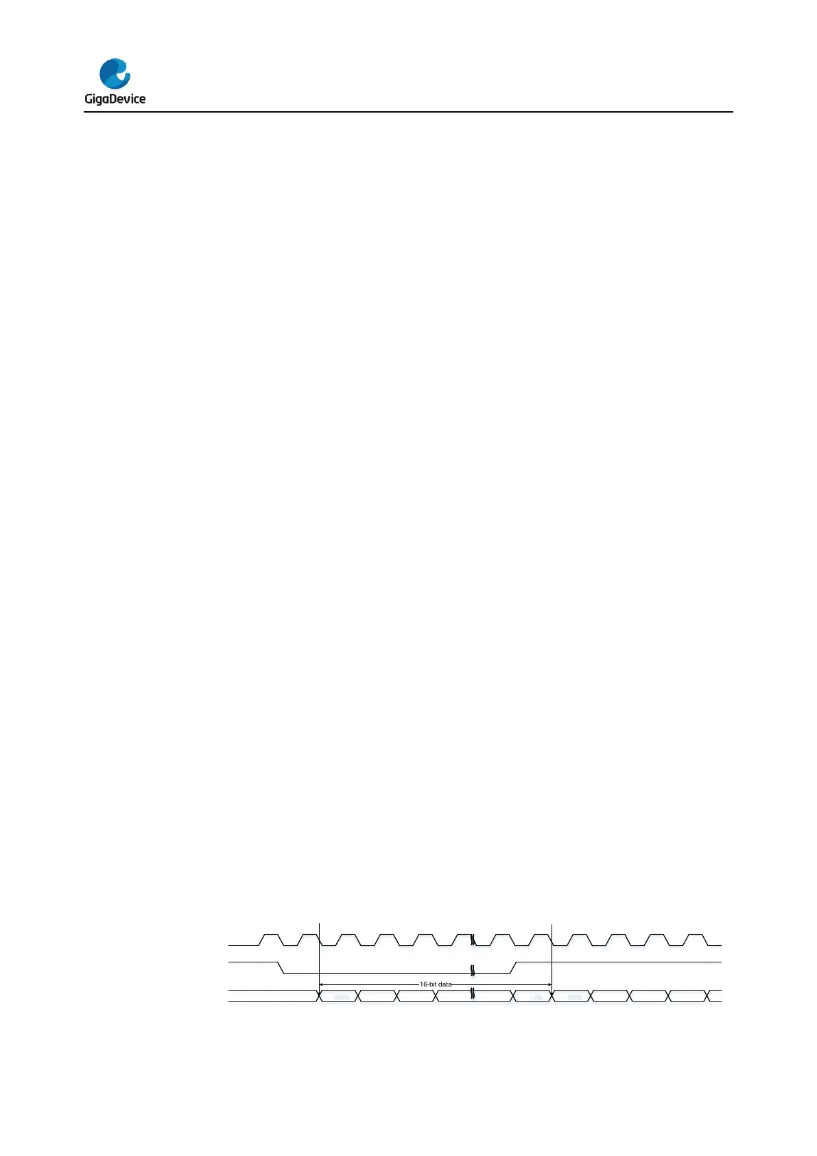
I2S Phillips standard
For I2S Phillips standard, I2S_WS and I2S_SD are updated on the falling edge of I2S_CK,
and I2S_WS becomes valid one clock before the data. The timing diagrams for each
configuration are shown below.
Figure 20-15. I2S Phillips standard timing diagram (DTLEN=00, CHLEN=0, CKPL=0)