GD32F3x0 User Manual
537
So, in order to get the desired audio sampling frequency, the clock generator needs to be
configured according to the formulas listed in Table 20-8. Audio sampling frequency
calculation formulas.
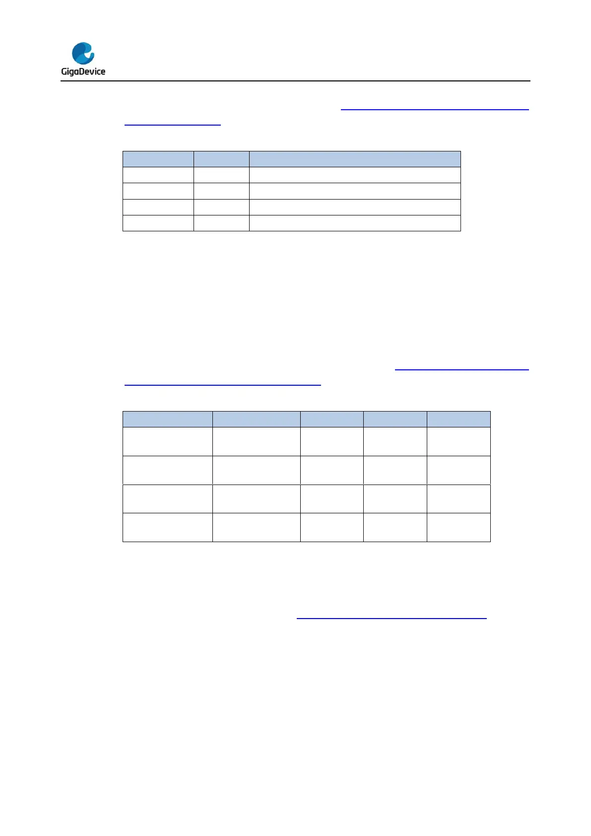
Table 20-8. Audio sampling frequency calculation formulas
I2SCLK / (32 * (DIV * 2 + OF))
I2SCLK / (64 * (DIV * 2 + OF))
I2SCLK / (256 * (DIV * 2 + OF))
I2SCLK / (256 * (DIV * 2 + OF))
20.4.5. Operation
Operation modes
The operation mode is selected by the I2SOPMOD[1:0] bits in the SPI_I2SCTL register.
There are four available operation modes, including master transmission mode, master
reception mode, slave transmission mode, and slave reception mode. The direction of I2S
interface signals for each operation mode is shown in the Table 20-9. Direction of I2S
interface signals for each operation mode.
Table 20-9. Direction of I2S interface signals for each operation mode
1. NU means the pin is not used by I2S and can be used by other functions.
I2S initialization sequence
I2S initialization sequence is shown as Figure 20-52. I2S initialization sequence.


 To Next Page