GD32F3x0 User Manual
490
5. After the last byte is received, RBNE is set. Software reads the last byte.
6. STPDET bit is set when I2C detects a STOP signal on I2C bus and software reads
I2C_STAT0 and then writes I2C_CTL0 to clear the STPDET bit.
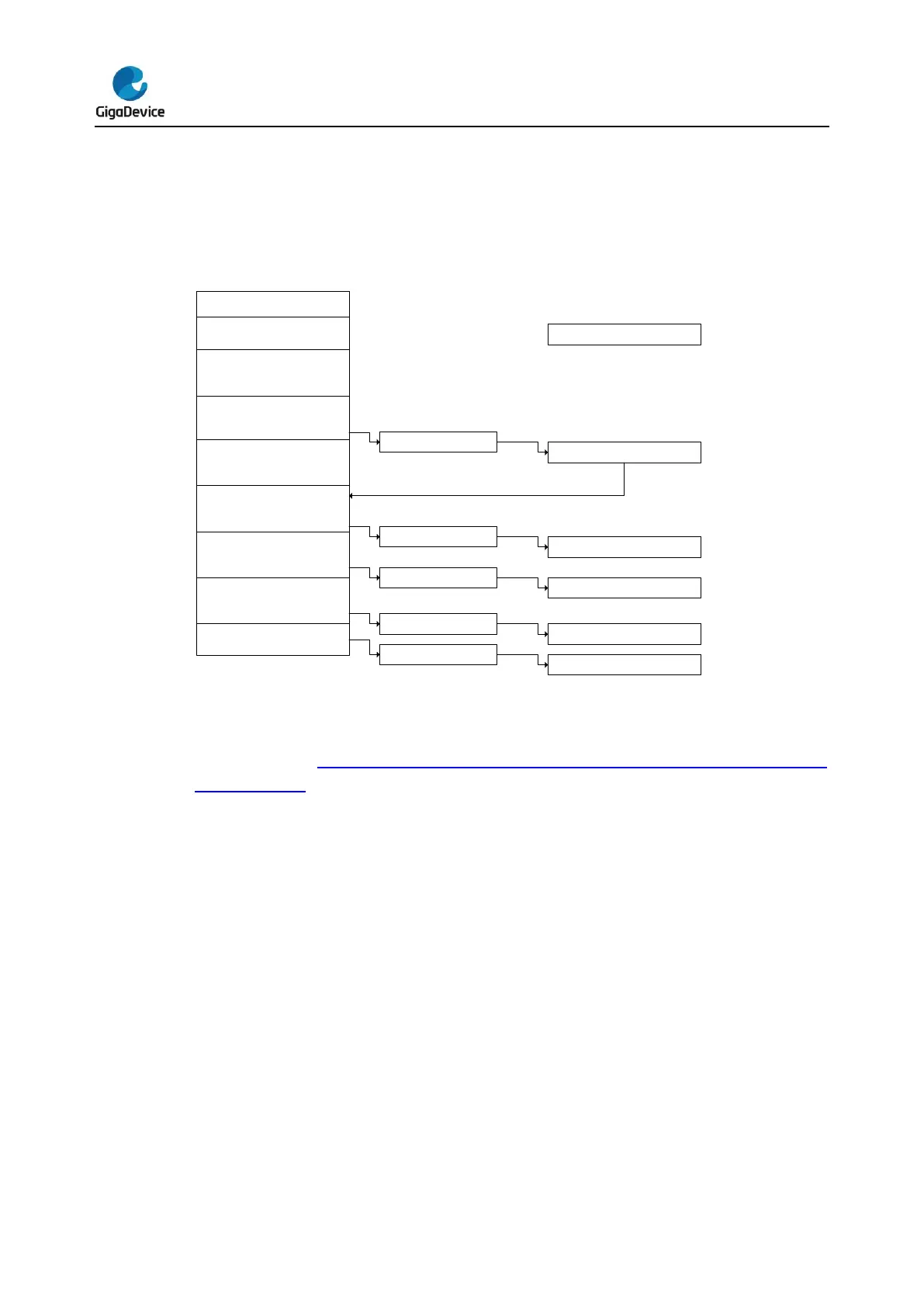
Figure 19-10. Programming model for slave receiving (10-bit address mode)
Programming model in master transmitting mode
As is shown in Figure 19-11. Programming model for master transmitting (10-bit
address mode), the following software procedure should be followed if users wish to make
transaction in master transmitter mode:
1. First of all, enable I2C peripheral clock as well as configure clock related registers in
I2C_CTL1 to make sure correct I2C timing. After enabled and configured, I2C operates
in its default slave state and waits for START signal followed by address on I2C bus.
2. Software sets START bit requesting I2C to generate a START signal on I2C bus.
3. After sending a START signal, the I2C hardware sets the SBSEND bit in I2C_STAT0
register and enters master mode. Now software should clear the SBSEND bit by
reading I2C_STAT0 and then writing a 7-bit address or header of a 10-bit address to
I2C_DATA. I2C begins to send address or header to I2C bus as soon as SBSEND bit is
cleared. If the address which has been sent is header of a 10-bit address, the hardware
sets ADD10SEND bit after sending the header and software should clear the
ADD10SEND bit by reading I2C_STAT0 and writing 10-bit lower address to I2C_DATA.
4. After the 7-bit or 10-bit address has been sent, the I2C hardware sets the ADDSEND bit
and software should clear the ADDSEND bit by reading I2C_STAT0 and then
 Loading...

