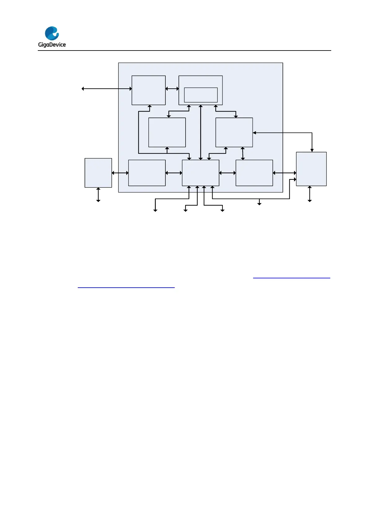
1.2. System architecture
The system architecture of GD32F3x0 series is shown in the Figure 1-2. Series system
architecture of GD32F3x0 series (For system architecture of the specific device, please
refer to the datasheet of the corresponding device). The AHB matrix based on AMBA 3.0
AHB-LITE is a multi-layer AHB, which enables parallel access paths between multiple
masters and slaves in the system. There are four masters on the AHB matrix, including
I-Code, D-Code, system bus of the Cortex
®
-M4 core and DMA. The I-Code bus is the
instruction bus and also used for vector fetches from the Code region (0x0000 0000 ~
0x1FFF FFFF) to the Cortex
®
-M4 core. The D-Code bus is used for loading / storing data
and also for debugging access of the Code region. Similarly, the System bus is used for
instruction / vector fetches, data loading / storing and debugging access of the system
regions. The System regions include the internal SRAM region and the Peripheral region.
The AHB matrix consists of five slaves, including I-Code and D-Code interfaces of the flash
memory controller, internal SRAM, AHB1 and AHB2.
The AHB2 connects with the GPIO ports. The AHB1 connects with the AHB peripherals
including two AHB-to-APB bridges which provide full synchronous connections between the
AHB1 and the two APB buses. The two APB buses connect with all the APB peripherals.
 Loading...

