GD32F3x0 User Manual
276
TIMER1 as prescaler for TIMER0
We configure TIMER1 as a prescaler for TIMER0. Refer to Figure 16-26. TIMER0
Master/Slave mode timer example for connections. Do as follow:
1. Configure TIMER1 in master mode and select its Update Event (UPE) as trigger output
(MMC=010 in the TIMER1_CTL1 register). Then TIMER1 drives a periodic signal on
each counter overflow.
2. Configure the TIMER1 period (TIMER1_CAR registers).
3. Select the TIMER0 input trigger source from TIMER1 (TRGS=001 in the
TIMER0_SMCFG register).
4. Configure TIMER0 in external clock mode 1 (SMC=111 in TIMER0_SMCFG register).
5. Start TIMER0 by writing ‘1 in the CEN bit (TIMER0_CTL0 register).
6. Start TIMER1 by writing ‘1 in the CEN bit (TIMER1_CTL0 register).
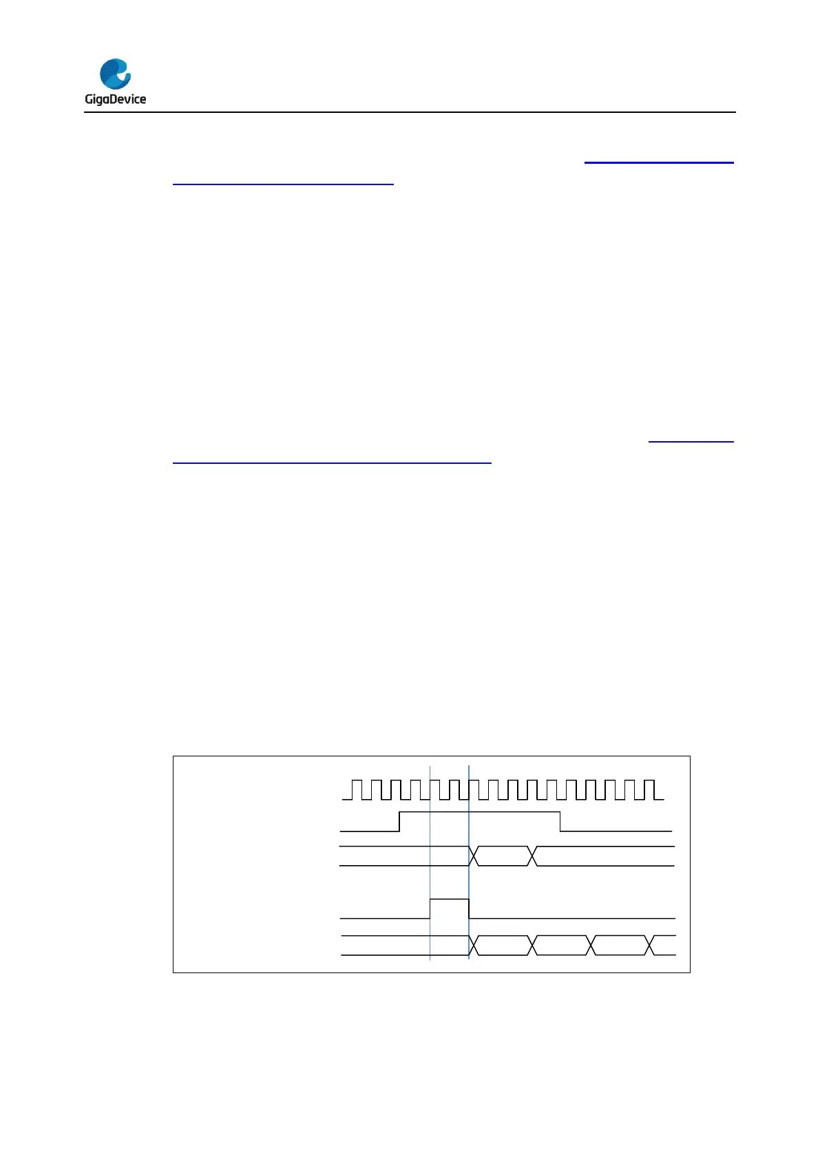
Start Timer0 with Timer1’s Enable/Update signal
In this example, we enable Timer0 with the enable output of Timer1. Refer to Figure 16-27.
Triggering TIMER0 with enable signal of TIMER1. Timer0 starts counting from its current
value on the divided internal clock after trigger by Timer1 enable output.
When Timer0 receives the trigger signal, its CEN bit is set and the counter counts until we
disable timer0. In this example, both counter clock frequencies are divided by 3 by the
prescaler compared to TIMER_CK (f
CNT_CLK
= f
TIMER_CK
/3). Timer0’s SMC is set as event
mode, so Timer0 can not be disabled by Timer1’s disable signal. Do as follow:
1. Configure Timer1 master mode to send its enable signal as trigger output (MMC=3’b001
in the TIMER1_CTL1 register)
2. Configure Timer0 to select the input trigger from Timer1 (TRGS=3’b001 in the
TIMERx_SMCFG register).
3. Configure Timer0 in event mode (SMC=3’b 110 in TIMERx_SMCFG register).
4. Start Timer1 by writing 1 in the CEN bit (TIMER1_CTL0 register).
Figure 16-27. Triggering TIMER0 with enable signal of TIMER1


 To Next Page