GD32F3x0 User Manual
180
11.4.14. On-chip hardware oversampling
The on-chip hardware oversampling circuit unit performs data preprocessing to offload the
CPU. It can handle multiple conversions and average them into a single data with increased
data width, up to 16-bit.
It provides a result with the following form, where N and M can be adjusted, and D
out
(n) is the
n-th output digital signal of the ADC:
Result =
1
M
*
∑
D
OUT
(
n
)
n=N-1
n=0
(11-1)
The on-chip hardware oversampling circuit performs the following functions: summing and
bit right shifting.The oversampling ratio N is defined by the OVSR[2:0] bits in the
ADC_OVSAMPCTL register. It can range from 2x to 256x. The division coefficient M means
bit right shifting up to 8 bits. It is configured through the OVSS[3:0] bits in the
ADC_OVSAMPCTL register.
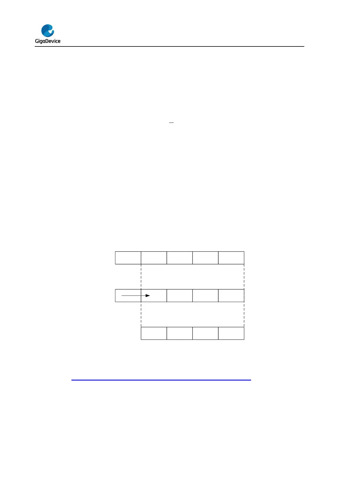
Summation units can produce up to 20 bits (256 x 12-bit), which is first shifted right. The
upper bits of the result are then truncated, keeping only the 16 least significant bits rounded
to the nearest value using the least significant bits left apart by the shifting, before being
finally transferred into the data register.
Figure 11-11. 20-bit to 16-bit result truncation
Note: If the intermediate result after the shifting exceeds 16 bits, the upper bits of the result
are simply truncated.
Figure 11-12. Numerical example with 5-bits shift and rounding shows a numerical
example of the processing, from a raw 20-bit accumulated data to the final 16-bit result.


 To Next Page