GD32F3x0 User Manual
174
1. Make sure the DISRC, SM in the ADC_CTL0 register and CTN bit in the
ADC_CTL1 register are reset.
2. Configure RSQ0 with the analog channel number.
3. Configure ADC_SAMPTx register.
4. Configure ETERC and ETSRC bits in the ADC_CTL1 register if it is needed.
5. Set the SWRCST bit, or generate an external trigger for the routine sequence.
6. Wait the EOC flag to be set.
7. Read the converted data result in the ADC_RDATA register.
8. Clear the EOC flag by writing 0 to it.
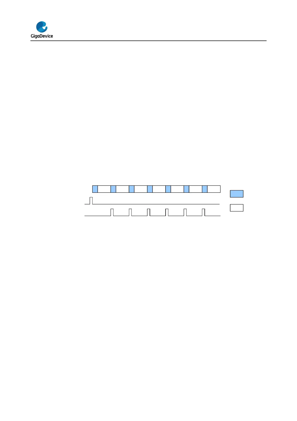
Continuous operation mode
The continuous operation mode will be enabled when the CTN bit in the ADC_CTL1 register
is set. In this mode, the ADC performs conversion on the channel specified in the RSQ0[4:0].
When the ADCON has been set high, the ADC samples and converts a specified channel,
once the corresponding software trigger or external trigger is active. The conversion data will
be stored in the ADC_RDATA register.
Figure 11-3. Continuous operation mode
Software procedure for continuous operation mode on a routine channel:
1. Set the CTN bit in the ADC_CTL1 register.
2. Configure RSQ0 with the analog channel number.
3. Configure ADC_SAMPTx register.
4. Configure ETERC and ETSRC bits in the ADC_CTL1 register if it is needed.
5. Set the SWRCST bit, or generate an external trigger for the routine sequence.
6. Wait the EOC flag to be set.
7. Read the converted data result in the ADC_RDATA register.
8. Clear the EOC flag by writing 0 to it.
9. Repeat steps 6~8 as soon as the conversion is in need.
To avoid checking, DMA can be used to transfer the converted data:
1. Set the CTN and DMA bit in the ADC_CTL1 register.
2. Configure the RSQ0 with the analog channel number.
3. Configure ADC_SAMPTx register.
4. Configure ETERC and ETSRC bits in the ADC_CTL1 register in if it is needed.
5. Prepare the DMA module to transfer data from the ADC_RDATA (refer to the spec
of the DMA module).
6. Set the SWRCST bit, or generate an external trigger for the routine sequence.


 To Next Page