Input capture and output compare channels
The general level0 TIMER has four independent channels which can be used as capture
inputs or compare match outputs. Each channel is built around a channel capture compare
register including an input stage, channel controller and an output stage.
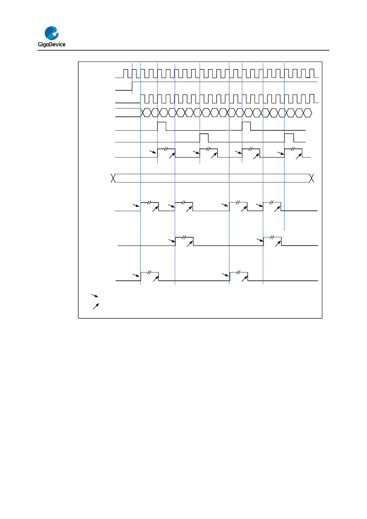
Channel input capture function
Channel input capture function allows the channel to perform measurements such as pulse
timing, frequency, period, duty cycle and so on. The input stage consists of a digital filter, a
channel polarity selection, edge detection and a channel prescaler. When a selected edge
occurs on the channel input, the current value of the counter is captured into the
TIMERx_CHxCV register, at the same time the CHxIF bit is set and the channel interrupt is
generated if enabled by CHxIE = 1.
 Loading...

