Replacing PSUs
The controller includes two redundant, hot-swappable power supply units (2 AC PSUs or 2 DC
PSUs). No chassis components need to be removed to add or replace a PSU.
Follow these steps to remove and replace a PSU.
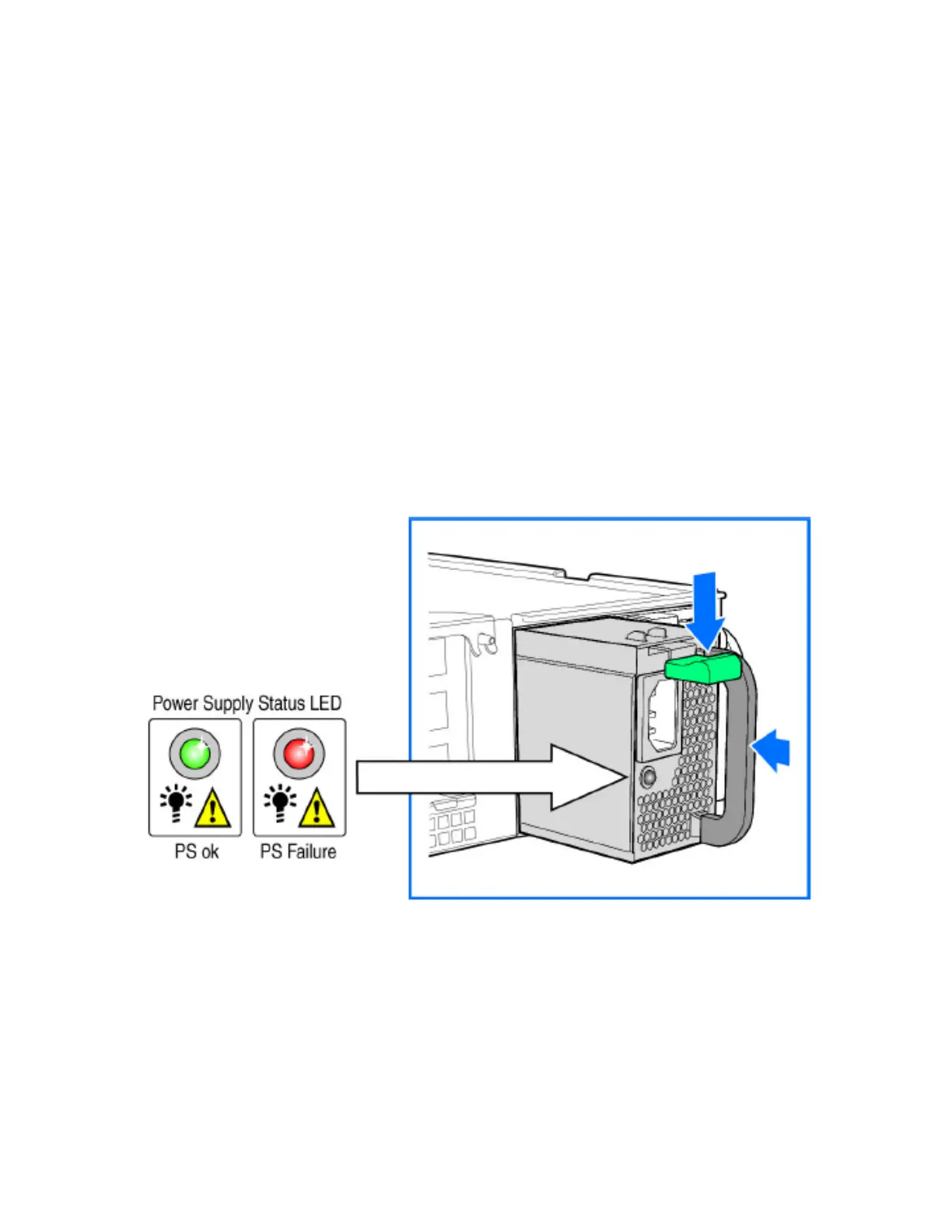
1. Identify the faulty PSU by looking at the PSU status LED (red indicates PSU failure, green
indicates normal operation).
2. Press and hold the green safety lock downward while grasping the PSU handle.
3. Pull outward on the handle, sliding the PSU all the way out of the rear of the machine.
4. Insert the new PSU into the slot and, while holding the green safety lock, slide the PSU into
the slot until it locks in place.
The PSU status LED turns green, indicating that the PSU is operating normally.
NOTE: If you are installing a DC power supply, there are two threaded studs for chassis enclosure
grounding. A 90" standard barrel, two-hole, compression terminal lug with 5/8-inch pitch suitable
for a #14-10 AWG conductor must be used for proper safety grounding. A crimping tool may
be needed to secure the terminal lug to the grounding cable.
Figure 265: Replacing a PSU
Replacing System Fans
The controller includes six redundant, hot-swappable system fans (four 80mm fans and two
60mm fans). There are also two fans located inside the power supply units. Redundancy for the
two PSU fans is only achieved when both PSUs are installed.
If any of the system fans requires replacement, the replacement procedure is identical.
SmartCell Gateway 200/Virtual SmartZone High-Scale for Release 3.4.1 Administrator Guide
449
Replacing Hardware Components
Installing or Replacing Hard Disk Drives