Intel
®
EP80579 Integrated Processor Product Line—Serial ATA (SATA) Interface
Intel
®
EP80579 Integrated Processor Product Line
Platform Design Guide May 2010
154 Order Number: 320068-005US
11.2 SATA Transmit and Receive Signals –
SATA_TXp[1:0], SATA_TXn[1:0], SATA_RXp[1:0],
SATA_RXn[1:0]
The SATA interface has two differential transmit and receive pairs for a total of 8
signals. Route each pair differentially as microstrip or stripline. Table 58 summarizes
the SATA_TX and SATA_RX routing guidelines.
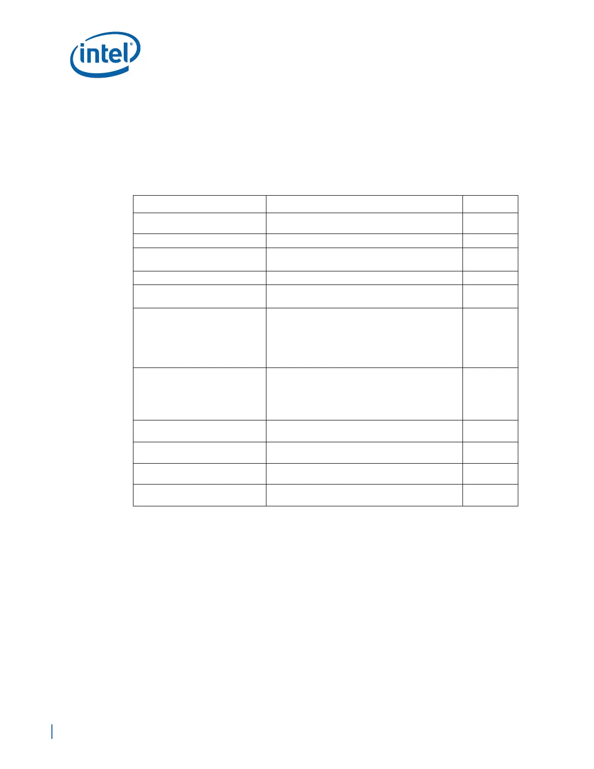
Table 58. Transmit and Receive Routing Guidelines
Parameter Routing Guidelines Figure
Signal Group
SATA_TXp[1:0], SATA_TXn[1:0], SATA_RXp[1:0],
SATA_RXn[1:0]
Reference Plane Ground Referenced, Stripline or Microstrip
Layer Assignment
Layer 1 or 10 (microstrip)
Layers 3 or 8 (stripline)
Characteristic Trace Impedance (Zo) 90 Ω ±10% (differential)
Nominal Trace Width
4.75 mils (microstrip)
4.5 mils (stripline)
Figure 101
Nominal Trace Spacing
Trace Spacing, edge-to-edge:
5.25 mils–microstrip
5.5 mils–stripline
Pair to Pair Spacing, edge-to-edge:
25 mils –microstrip
20 mils –stripline
Figure 101
Nominal Trace Length
L1 max = 0.400 in.
L2 =
Stripline –> min = 1.150 in., max = 4.750 in.
Microstrip –> min = 1.500 in., max = 5.750 in.
L3 max = (L-ac1 + L_ac_2) = 0.350 in.
Figure 99 and
Figure 100
Length Tuning Requirements LTpos = LTneg within 5 mils (LT = L1+L2+L3)
Figure 99 and
Figure 100
EP80579 Breakout
4 mils width with 4 mils spacing for maximum of
400 mils, minimize this length.
Figure 99 and
Figure 100
Vias
2 Vias max, recommended to remove unused internal
pads to improve the signal quality.
Figure 99 and
Figure 100
AC CAP 10 nf
Figure 99 and
Figure 100