Intel
®
EP80579 Integrated Processor Product Line May 2010
Order Number: 320068-005US 100
Platform System Clock—Intel
®
EP80579 Integrated Processor Product Line
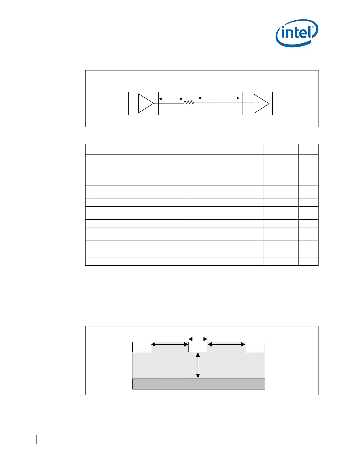
Figure 59. Topology for CLK33 to Down Devices
Table 21. CLK33 Routing Guidelines to EP80579, FWH, and LPC Down Devices
Parameter Routing Guidelines Illustrations Notes
Clock Group CLK33: 33 MHz clocks - Port80,
FWH, LPC, TPM, SIO,
ICH_33MHz_CLK,
ITP_PCI_CLK_33MHz
Topology Point-to-point Figure 59
Reference Plane Ground referenced (contiguous
over entire length)
1
Characteristic Trace Impedance (Z
0
)55 Ω ± 10%
Trace Width (W) microstrip: 4.5 mils
stripline: 4.75 mils
Figure 60 2
Trace Spacing (S1) 20 mils Figure 60
EP80579, FWH, and other LPC down devices
Trace Length (L1)
0.5” max
Figure 59
EP80579 (L2) L2 = Z = 2” to 20” Figure 59 3, 4
FWH, Port80, TPM, SIO Trace Length (L2) L2 = [Z + (0” to 6”)] = 20” max Figure 59 3, 4
Resistor Rs = 43 Ω
±5% Figure 59 4
Note:
1. Ground referencing is preferred. However, CLK33 can be routed referenced to other planes if the
plane is contiguous from source to destination
2. Trace width is stackup dependent. Routing guidelines are for the width is 4.5 mils with 6.25 mil
spacing on layers 3 & 8.
3. Length Z = L1 + L2, from Figure 58.
4. The value of Rs may need to be increased for shorter trace lengths to minimize overshoot /
undershoot effects.
Figure 60. Trace Spacing for CLK33 (PCICLK) Clock
L1
L2
Clock
Driver
Rs
EP80579 or Down
Devices