Intel
®
EP80579 Integrated Processor Product Line—Low Pin Count (LPC) Interface
Intel
®
EP80579 Integrated Processor Product Line
Platform Design Guide May 2010
188 Order Number: 320068-005US
The routine and topology guidelines in Figure 125 are based on the following:
•Ten layer stack up
• LPC routing used layer 8
•Trace impedance 50Ω ±10%
• LPC clock traces should be trace length matched. Maximum trace length mismatch
between clocks coming from the clock driver should be no greater that 250 mils.
Figure 126 and Table 70 show the EP80579’s LPC interface design recommendation
routing for all signals except clock:
• Daisy chain all signals to every device on the bus
• Use a total of five or fewer devices on the LPC bus
• The EP80579 can be placed anywhere in the bus daisy chain (can be in the middle
or at the end of the chain)
• There is no length matching requirement among the signals, as long as each signal
meets the length target
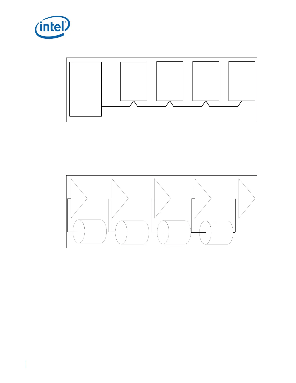
Figure 124. Development Board LPC Interface Block Diagram
LPC Interface
Buffer to
Por t 80
Fi r mWare Hub
(FWH)
Trust ed-
Platform
Modul e
(TPM)
Super
IO
EP80579
Figure 125. Topology of LPC Interface
Device 1
TL1
TL2 TL3
TL4
Device 2 Device 3 Devi ce 4 Devi ce 5

 Loading...


