Intel
®
EP80579 Integrated Processor Product Line May 2010
Order Number: 320068-005US 159
Serial ATA (SATA) Interface—Intel
®
EP80579 Integrated Processor Product Line
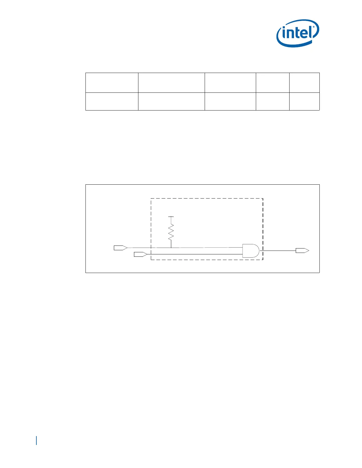
11.6 SATALED# Implementation
EP80579 provides a signal (SATALED#) to indicate SATA device activity. In order for
this signal to work in conjunction with Parallel ATA hard drives, it is recommended that
designers implement similar glue logic as illustrated in Figure 103.
When low, SATALED# indicates SATA device activity and must activate the hard drive’s
LED. When tristated, the signal will not activate the LED. The hard drive LED is active
low.
11.7 SATA Host Connector Placement Considerations
When placing SATA host connectors, applicable keep-out regions must be
comprehended in the layout of the board. Figure 104 shows an example cable and the
height required for bending the cable to a 90º bend. This can be used as an example
when considering height obstruction regions.
Table 59. SATA_RBIAS/SATA_RBIAS# Routing Summary
Trace Impedance
SATA_RBIAS/
SATA_RBIAS# Routing
Requirements
Maximum Trace
Length
Signal
Length
Matching
Signal
Referencin
g
50 Ω ±15% (single
ended)
Short SATA_RBIAS and
SATA_RBIAS# pins at the
package.
A = 0.0” - 0.5”
(EP80579 to Resistor)
N/A N/A
Figure 103. SATALED# Circuitry Example
From IDE Connector
SATALED#
Hard Drive LED
Vcc3_3
Glue Logic

 Loading...


