Intel
®
EP80579 Integrated Processor Product Line—System Power Delivery Guide
Intel
®
EP80579 Integrated Processor Product Line
Platform Design Guide May 2010
80 Order Number: 320068-005US
NOTES:
1. Filter DC resistance is the inductor resistance + MB routing resistance.
2. Vout measurement taken as close to (G)MCH package as possible.
6.6.7 Thermal Power Dissipation
Power dissipation has traditionally been a thermal/mechanical challenge for embedded
system designers. The amount of current required from the processor power delivery
circuit and the heat generated by processors has increased as processor frequencies go
up and the silicon process geometry shrinks. The package of any integrated device can
dissipate a limited amount of heat into the surrounding environment. The temperature
of a device, such as a processor power delivery circuit-switching transistor, is a balance
of heat being generated by the device and its ability to shed heat either through
radiation into the surrounding air or by conduction into the circuit board. Increased
power may effectively raise the temperature of the processor power delivery circuits.
Switching transistor die temperatures may exceed the recommended operating value
when the heat cannot be removed from the package effectively.
As the current demands for higher frequency and performance processors increases,
the amount of power dissipated (i.e., heat generated) in the processor power delivery
circuit is starting to become of concern for the applied computing system, thermal, and
electrical design engineers. The high input voltage, low duty factor inherent in power
supply designs leads to increasing power dissipation losses in the output stage of the
traditional buck regulator topology used in the industry today.
These losses may be attributed to three main areas of the processor power delivery
circuit.
• The switching MOSFET dissipates a significant amount of power during switching of
the top control MOSFET.
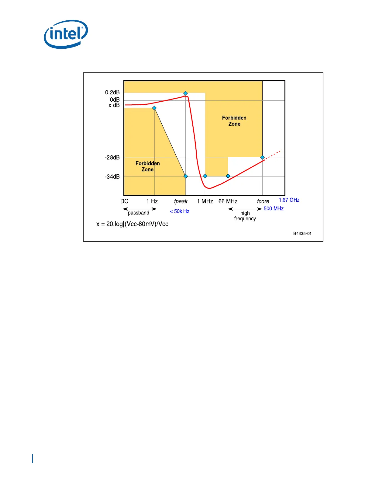
Figure 48. Filter Frequency Response Specification
B4335-01
Forbidden
Zone
Forbidden
Zone
fpeak fcore
!""#!$%!""
&'&
()*+,*"-
./