Intel
®
EP80579 Integrated Processor Product Line—Debug Port Design Guide
Intel
®
EP80579 Integrated Processor Product Line
Platform Design Guide May 2010
262 Order Number: 320068-005US
Notes:
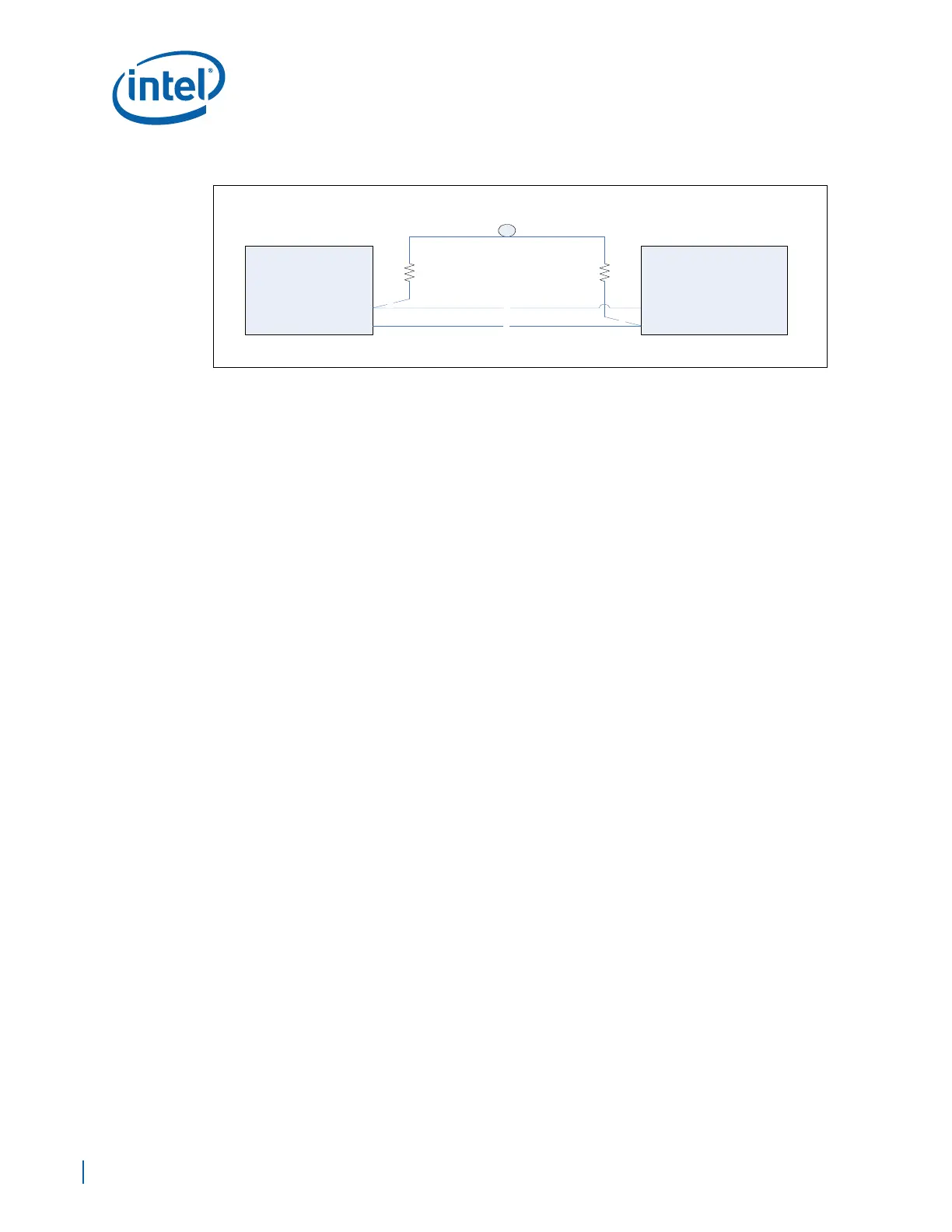
(A) - These traces have no specific routing requirements.
(B) - This routing has no length requirements.
26.3.1.2 TCK0 and TCK1 Routing
Route TCK0 to the EP80579 TCK with a 51 ohm 5% resistor to GND at the EP80579
end. The trace length must be a maximum of 1.5ns. Any stub on this net must be
shorter than 200ps.
Note: Leave TCK1 as a NO CONNECT.
26.3.1.3 TMS Routing Guidelines
This JTAG signal is routed as a daisy chain to all devices. There should be a 51 ohm 5%
resistor to VTAP placed at the last load on the trace.
There is no trace-length requirement for this signal.
26.3.1.4 TRSTn Routing Guidelines
This JTAG signal is routed as a daisy chain to all devices on all chains. There should be
a 51 ohm 5% pull-down resistor on the trace. The location of this resistor is
recommended to be near the last device in the chain, but can be placed in other
positions if necessary for platform layout. The trace length of this signal is unimportant.
26.3.2 Observation Port Routing Guidelines
There are four observation ports on the XDP labeled A through D. Each observation port
is made up of four OBS Data lines and two OBSFN control/strobe lines. The observation
ports of this debug port are used to support the following features:
26.3.2.1 Pilot Bus (NOA) Routing Guidelines
This signal is reserved. No connection to this signal are required.
26.3.2.2 BPM4_PRDY_OUT (BPM4) Routing Guidelines
Route point-to-point from EP80579 to the XDP debug port. Stubs on these nets must
be no longer than 200ps. There are no specific routing lengths required for these nets.
Note: This signal may also be referred to as PRDY#. No termination is required on the
platform for this signal.
Figure 155. TDI-TDO Routing
51
5%
VTAP
51
5%
B
TDI
TDO
XDP Debug
Port
TDI
TDO
A
A
B
EP80579