Intel
®
EP80579 Integrated Processor Product Line May 2010
Order Number: 320068-005US 187
Low Pin Count (LPC) Interface—Intel
®
EP80579 Integrated Processor Product Line
14.2 LPC Layout
14.2.1 General Routing and Placement
Use the following general routing and placement guidelines when laying out a new
design:
• LPC signals should be ground referenced.
• Route all traces using microstrip or stripline over continuous planes (Vcc or GND)
with no interruptions. Avoid crossing over anti-etch if at all possible. Any
discontinuity or split in the ground plane may cause signal reflections and should be
avoided.
• Route LPC signals using a minimum of vias and corners. This reduces reflections
and impedance changes.
• No 90-degree bends or stubs.
14.2.2 LPC Interface Routing and Topology
This section provides guidelines for topology routing. The Development Board provides
four basic component devices connected to the EP80579’s LPC interface. These devices
include:
•port 80
•Firmware Hub
• Trusted Platform Module
•Super IO
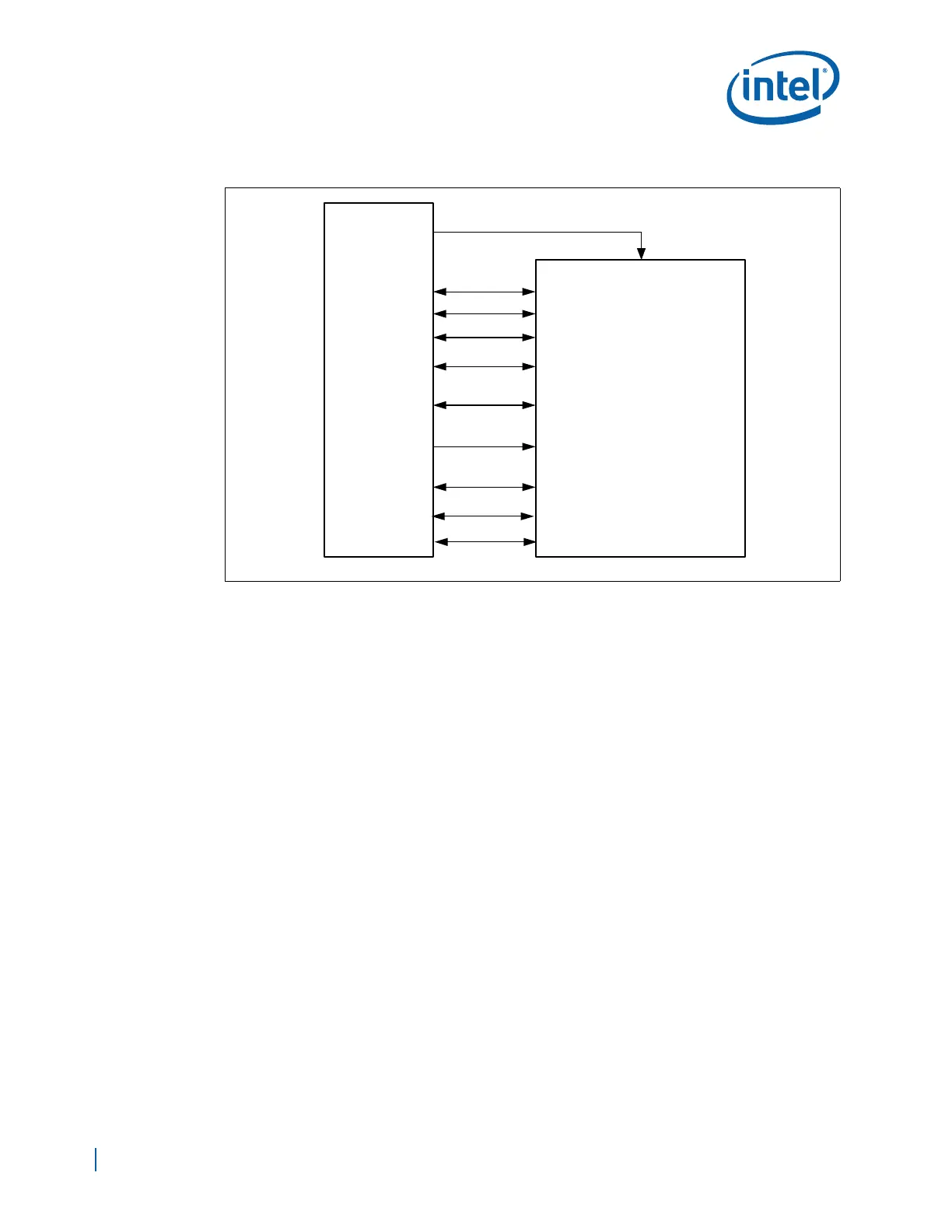
Figure 124 provides a block diagram:
Figure 123. LPC Interface Diagram
LAD[3:0]
SERIRQ
SUS_STAT#
LFRAME#
LPC Interface
PLTRST#
or
PCIRST#
LRESET#
SMBCLK/DATA
(optional)
EP80579
LDRQ#
(optional)
LPCPD#
(optional)
PCICLK or CLK 33 MHz
PME#
(optional)
LSMI#
(optional)
GPI

 Loading...


