Intel
®
EP80579 Integrated Processor Product Line—Local Expansion Bus (LEB) Interface
Intel
®
EP80579 Integrated Processor Product Line
Platform Design Guide May 2010
245 Order Number: 320068-005US
.
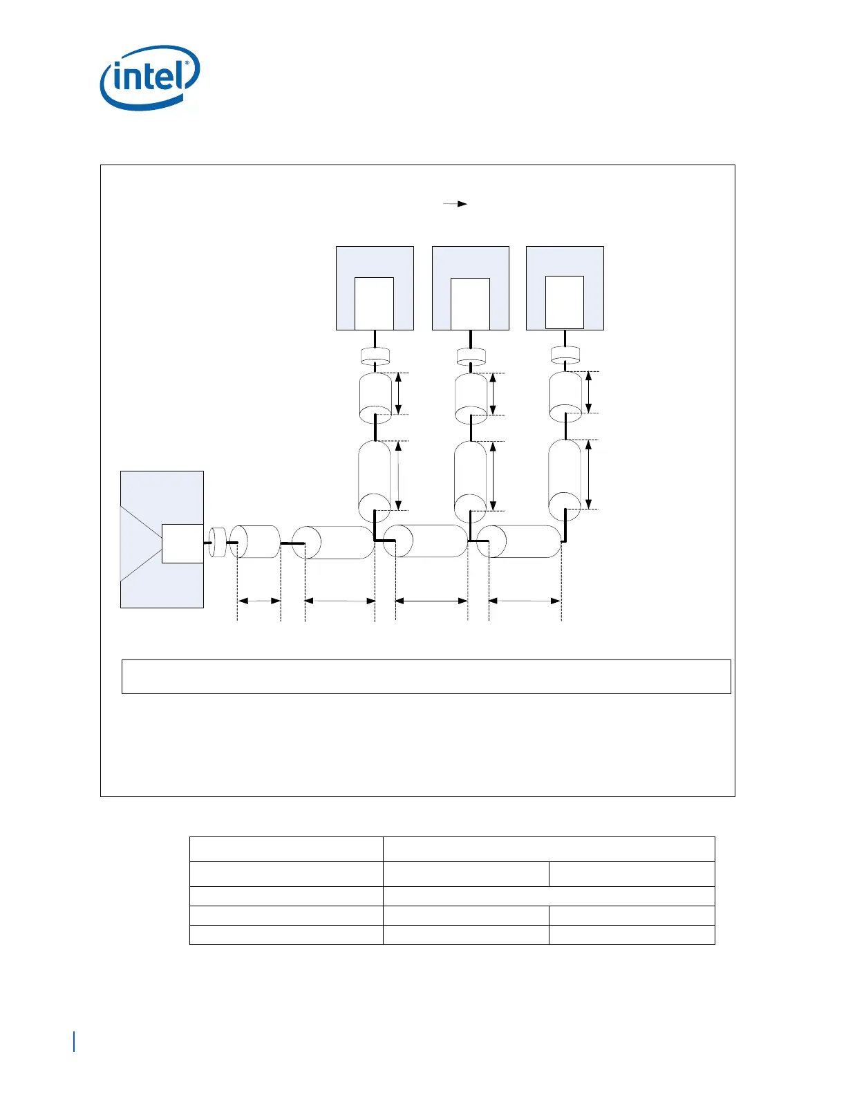
Figure 150. Address, Data, and Control Signals Mezzanine Star Topology Diagram
Table 91. Address, Data and Control Star Topology Routing Guidelines (Sheet 1 of 2)
Parameter Routing Constraints
Routing Layer Stripline Microstrip
Reference Plane Ground Referenced
Board Trace Impedance 50 Ω 50 Ω
Trace Width 4.5mils (L3/L8) 5.5mils (L1/L10)
Via Break out
BUFFER
LADDR_Brk_out LADDR_TL1_route
LADC_Total = LADC_Brk_out + LADC_TL1_route + 2XLADC_TL2_route + LADC_TL3_route + LADC_Brk_in
NOTE: Breakout\ Breakin descriptions are as follows:
1. Routing where trace is 4 mil wide and 4mil spacing is implemented to escape\ enter BGA
2. The Breakout \ Breakin Length is defined from the pin of the BGA, to where 4 mil spacing
increases to the required spacing per SI recommendations.
a). CS = 10 mil edge-to-edge (e2e) for Stripline
b). CS = 12 mil edge-to-edge (e2e) for Microstrip
Address, Data and Control Star Topology
(Buffer Mezzanine)
TL1
LADDR_TL3_route
TL3
TL2
TL2
Break in
LADDR_Brk_in
ADDR
Via
TL3
Break in
LADDR_Brk_in
ADDR
Via
TL3
Break in
LADDR_Brk_in
ADDR
Via
LADDR_TL2_route LADDR_TL2_route
LADDR_TL3_route
LADDR_TL3_route
MEZZ #1 MEZZ #2MEZZ #3
ADDR
DATA
CNTL