Intel
®
EP80579 Integrated Processor Product Line May 2010
Order Number: 320068-005US 116
System Memory Interface (DIMM)—Intel
®
EP80579 Integrated Processor Product Line
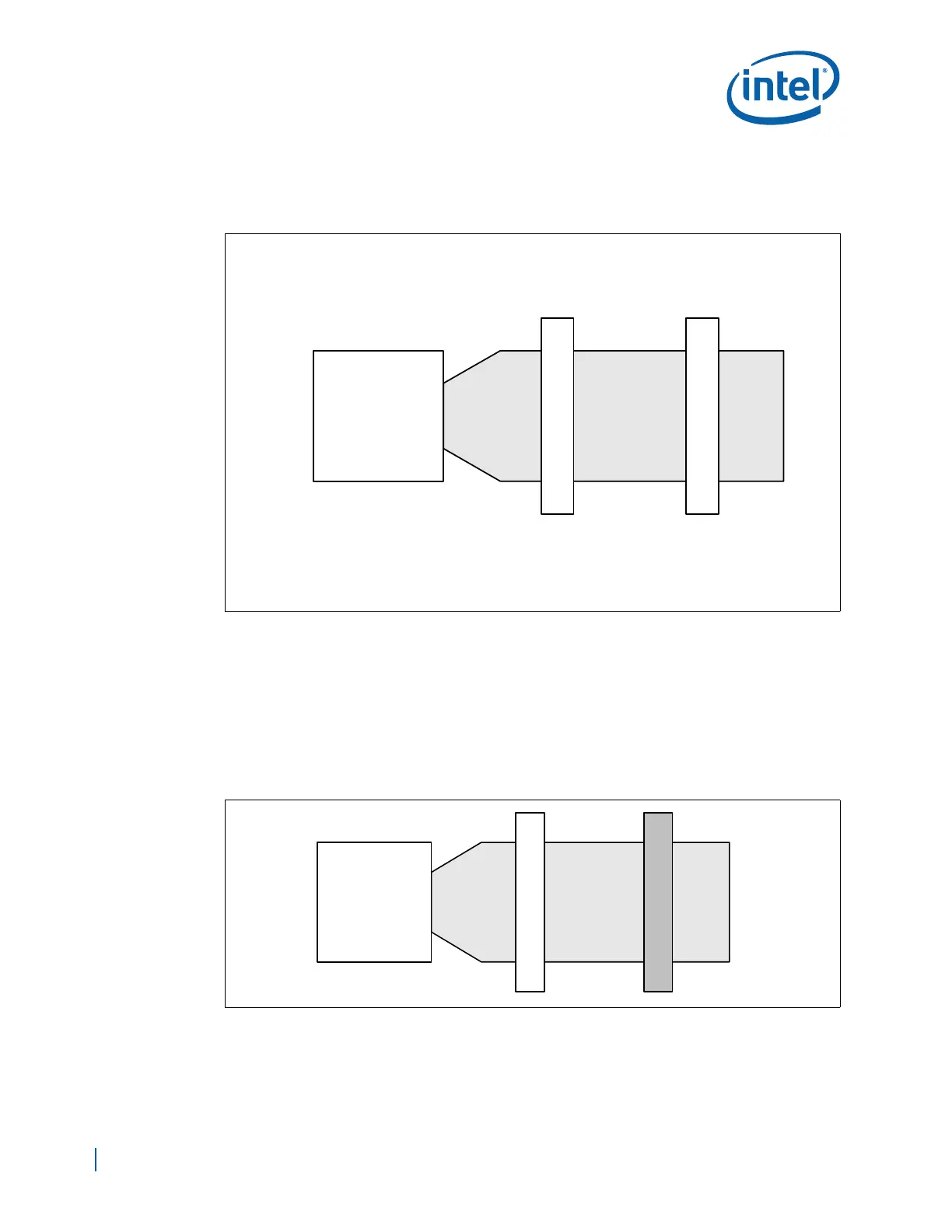
9.3.3 DDR2 DIMM Ordering Overview
Figure 71 shows the DIMM ordering and location.
A platform design requires single rank DDR2 DIMMs to be populated in order, starting
with the DIMM furthest from EP80579 (DIMM0 - primary DIMM) in a “fill-farthest”
approach (see Figure 71). In addition, dual-rank DIMMs must be populated farthest
from the EP80579 since only one dual rank DIMM is supported. This recommendation is
based on the chip select and on-die termination signals routing requirements of the
DDR2 interface. Intel recommends checking for correct DIMM placement during BIOS
initialization. Additionally, all designs should follow the DIMM ordering, clock enable
routing, command clock routing, and chip select routing documented in Figure 71. This
addressing must be maintained to be compliant with the reference BIOS code.
Figure 71. DDR-DIMM- Implementation
EP80579
D
I
M
M
0
0/1
0/0# & 1/1# & 2/2#
0/1
D
I
M
M
1
CKE
Command Clock:
Chip Select/ODT:
2 DIMM solution
1
3/3# & 4/4# & 5/5#
1
Figure 72. Example of One Single-Rank DIMM Population
EP80579
Empty 1
Single Rank DIMM 0