Intel
®
EP80579 Integrated Processor Product Line—Universal Serial Bus (USB) Interface
Intel
®
EP80579 Integrated Processor Product Line
Platform Design Guide May 2010
174 Order Number: 320068-005US
Example: Two 24-gauge (AWG) power or ground wires can be replaced with one 20-
gauge wire.
Proper wire gauge selection is important to meet the voltage drop and droop
requirements called out in the USB 2.0 Specification at the USB connectors as well as
at the stake pins on the PCB.
Placing the capacitance near the USB connectors for cables that share power and
ground conductors is required to ensure the system passes droop requirements. Cables
that provide individual power and ground conductors for each port can usually meet
droop requirements by providing adequate capacitance near the motherboard mating
connector since droop is actually an effect felt by adjacent ports due to switching
transients on the aggressor port. In the separate conductor case, all transients will be
seen/dampened by the capacitance at the motherboard mating connector before they
can cause problems with the adjacent port sharing the same cable. See Sections 7.2.2
and 7.2.4.1 of the USB 2.0 Specification for more details.
Cables that contain more than two signal pairs are not recommended due to
unpredictable impedance characteristics.
12.7.2 Motherboard/PCB Mating Connector
Proper selection of a motherboard mating connector for front panel USB support is
important to ensure signal quality is not adversely affected due to a poor connector
interface. The cable and PCB mating connector must also pass the TDR requirements
listed in the USB 2.0 Specification.
12.7.2.1 Pin-out
A ten pin, 0.1-inch pitch stake pin assembly is recommended with the schematic shown
in Figure 117 and the pin-out listed in Table 66.
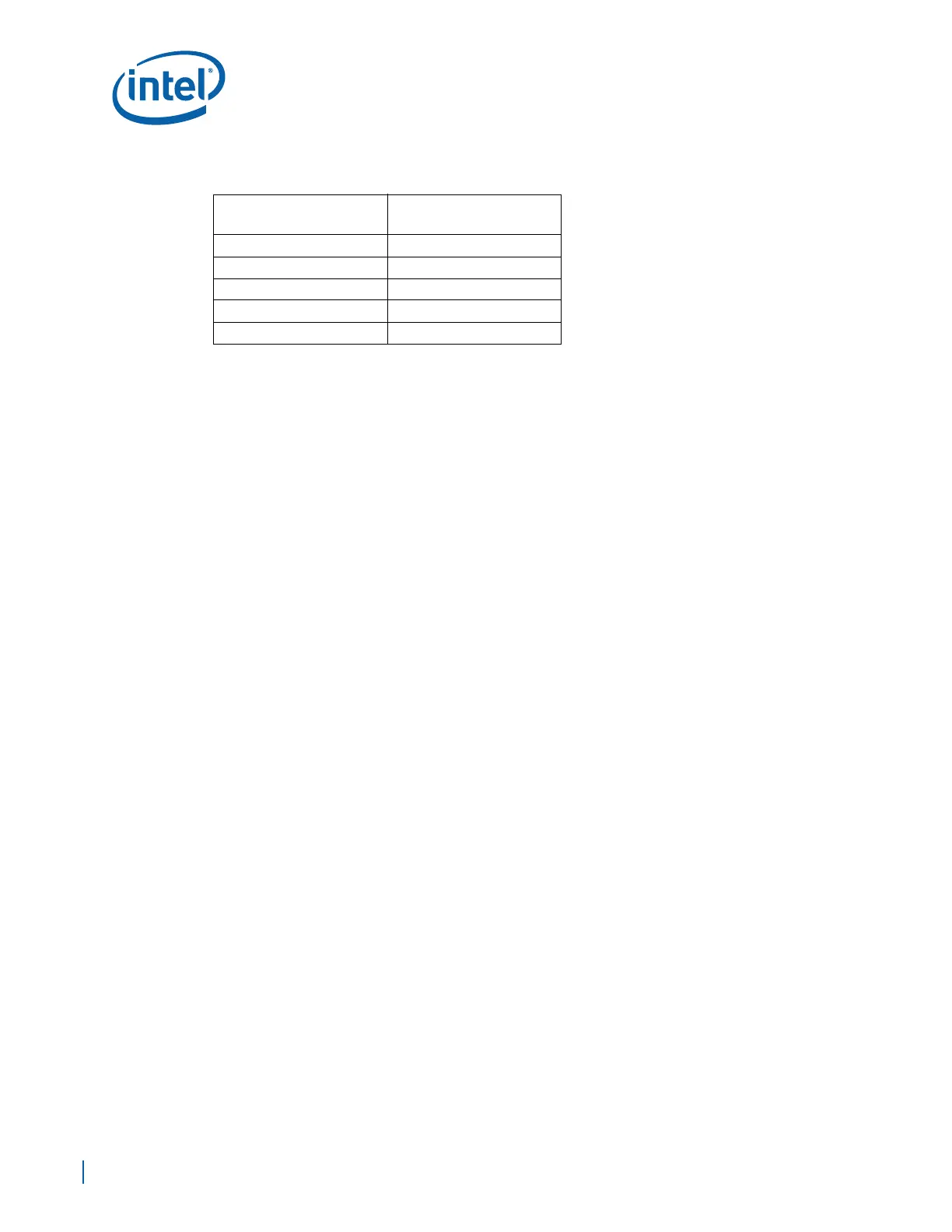
Table 65. Conductor Resistance (Table 6-6 from USB 2.0 Specification)
American Wire Gauge
(AWG)
Ohm/100 Meters
Maximum
28 23.20
26 14.60
24 9.09
22 5.74
20 3.58