Intel
®
EP80579 Integrated Processor Product Line—Time Division Multiplex (TDM) Interface
Intel
®
EP80579 Integrated Processor Product Line
Platform Design Guide May 2010
250 Order Number: 320068-005US
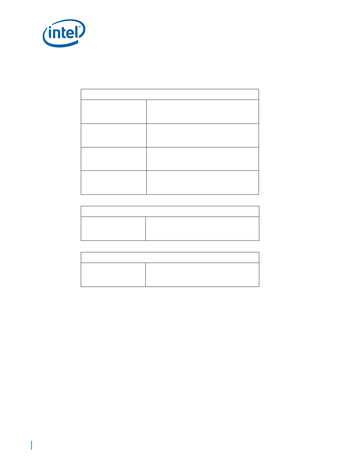
23.3.1 Input/Output Signal Application
The TDM controller has a total of 6 input/output signals per TDM port, as shown in the
following tables:
Note: The signals shown in the tables are single ended LVTTL 3.3V logic, and they are NOT 5V
tolerant.
23.3.2 Design Notes
The TDM interface does not fall into the high speed design category and therefore high
speed design rules are not required. When designing hardware for the TDM interface,
use routing and signal integrity rules that apply to the 10 MHz signals speeds. If the
use of LEB is required to control SLIC/CODECs, see the design rules for that particular
peripheral and design for the speed at which the bus will be running.
Inputs/Output
TX_FRAME[2:0]
• Transmit Frame Channel 0, 1 and 2
• Must be tied high to a 10K ohm resistor when
the port is not connected to an interfacing
device.
RX_FRAME[2:0]
• Receive Frame, Channel 0, 1 and 2
• Must be tied high to a 10K ohm resistor when
the port is not connected to an interfacing
device.
TX_CLK[2:0]
• Transmit Clock Channel 0, 1 and 2
• Must be tied high to a 10K ohm resistor when
the port is not connected to an interfacing
device.
RX_CLK[2:0]
• Receive Clock, Channel 0, 1 and 2
• Must be tied high to a 10K ohm resistor when
the port is not connected to an interfacing
device.
Output
TX_DATA_OUT[2:0]
• Transmit Data Channel 0, 1 and 2
• Must be tied high to a 10K ohm resistor when
the port is not connected to an interfacing
device.
Input
RX_DATA_IN[2:0]
• Receive Data Channel 0, 1 and 2
• Must be tied high to a 10K ohm resistor when
the port is not connected to an interfacing
device.

 Loading...


