Intel
®
EP80579 Integrated Processor Product Line May 2010
Order Number: 320068-005US 240
Local Expansion Bus (LEB) Interface—Intel
®
EP80579 Integrated Processor Product Line
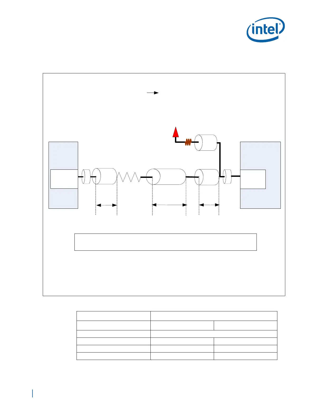
Figure 147 and Table 89 indicate min and max trace lengths that can be used when
routing chip select signals.
Figure 147. Chip Select Point-to-Point Topology Diagram
Table 89. Chip Select Point-to-Point Topology Routing Guidelines (Sheet 1 of 2)
Parameter Routing Constraints
Routing Layer Stripline Microstrip
Reference Plane Ground Referenced
Board Trace Impedance 50 Ω 50 Ω
Trace Width 4.5mils (L3/L8) 5.5mils (L1/L10)
Chip Select to Other Signals Spacing 10 mils (min) 12 mils (min)
VCC3
Via
Break out
Break in Board
CS
PeripheralEP80579
Rpull_up
LCS_Brk_out
LCS_Brd_route LCS_Brk_in
LCS_Brk_out + LCS_Brd_route + LCS_Brk_inLCS_Total =
NOTE: Breakout\ Breakin descriptions are as follows:
1. Routing where trace is 4 mil wide and 4mil spacing is implemented to escape\ enter BGA
2. The Breakout \ Breakin Length is defined from the pin of the BGA, to where 4 mil spacing
increases to the required spacing per SI recommendations.
a). CS = 10 mil edge-to-edge (e2e) for Stripline
b). CS = 12 mil edge-to-edge (e2e) for Microstrip
CS
Via
Chip Select Point-to-Point Topology
(EP80579 Peripheral)
10K ohm
22 ohm 1%