Intel
®
EP80579 Integrated Processor Product Line—Serial ATA (SATA) Interface
Intel
®
EP80579 Integrated Processor Product Line
Platform Design Guide May 2010
158 Order Number: 320068-005US
11.2.3 SATA AC Coupling Requirements
EP80579 requires AC coupling capacitors (10 nf) for both the SATA_TX and SATA_RX
differential pairs. The series capacitors may be placed at any point on the traces
between EP80579 and the SATA connector. However, it is recommended that they
should be closed to the connector for optimal signal quality. Layouts must minimize the
placement mismatch within a differential pair between the capacitors as much as
possible; in other words, the distance between EP80579 and the capacitor on the ‘P’
signal must be identical to the distance between EP80579 and the capacitor on the ‘N’
signal for the same pair.
11.3 SATA General Purpose Signals – SATA1_GP, SATA0_GP
EP80579 has two SATA General Purpose input signals, SATAx_GP. These signals can be
configured as interlock switch inputs corresponding to a given SATA port. When used as
an interlock switch status indication, drive this signal to ‘0’ to indicate the switch is
closed and to a ‘1’ to indicate the switch is open.
If interlock switches will not be used on the platform, these signals can be configured
as GPIs.
Note: All SATAx_GP pins must be configured with the same function, either SATAx_GP signals
or GPI signals.
Note: Each SATAx_GP pin that is not used must be terminated using an 8.2–10 kΩ pull-up
resistor to VCC33.
11.4 SATA Clock Signals – SATA_CLKREFp, SATA_CLKREFn
These 100 MHz differential clock signals are discussed in Section 8.2.2, “CLK100 (SRC
Clock) Group” on page 96.
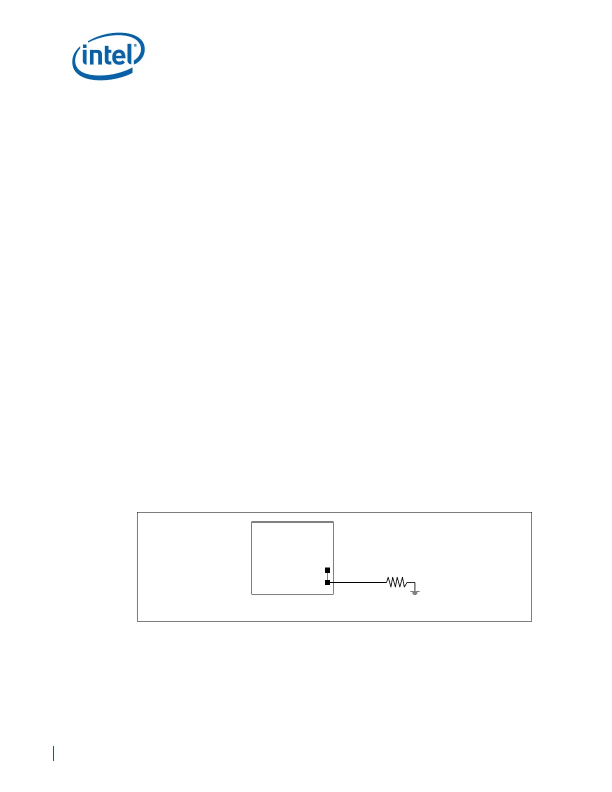
11.5 SATA_RBIAS/SATA_RBIAS# Connection
It is recommended that the SATA_RBIAS and the SATA_RBIAS# pins be shorted at the
package and then routed to one end of a 24.9 Ω ±1% resistor to ground. Place the
resistor within 0.0” to 0.5” of EP80579. Avoid routing next to clock pins.
Figure 102. SATA_RBIASp/SATA_RBIASn Connection
SATA_RBIAS
SATA_RBIAS#
24.9 Ω ± 1%
EP80579
A