Intel
®
EP80579 Integrated Processor Product Line—Platform System Clock
Intel
®
EP80579 Integrated Processor Product Line
Platform Design Guide May 2010
95 Order Number: 320068-005US
8.2.1.2 Host_CLK General Routing Guidelines
The host bus clocks delivered to the processor can be either microstrip or stripline
routing but must be ground referenced to minimize dielectric and impedance
variations. Do not split up the two halves of a differential clock pair between layers.
Route clocks to agents on the same physical routing layer. See Table 18 for detailed
requirements.
Table 18. HOST_CLK Routing Guidelines
Parameter Routing Guidelines Figure
Signal Group
Host_CLK:
• EP80579 (CLKP100/CLKN100)
• ITP Debug Port (BCLKP/BCLKN)
Reference Plane Ground Referenced, Microstrip or stripline
Layer Assignment Layers 3 or 8
Characteristic Trace Impedance (Zo) 100 Ω ±10% (differential)
Trace Width – W microstrip: 4.5 mils
stripline: 4.75 mils
Figure 54
Spacing within HOST_CLK pairs – S 10 mils Figure 54
HOST_CLK to Signal Spacing – S1 20 mils Figure 54
Serpentine Spacing 20 mils Figure 54
Routing Length – L1, L1’: Clock Driver to Rs 0.5 in. max (Differential) Figure 53
Routing Length – L2, L2’: Rs to Rs-Rt Node 0.2 in. max (Differential) Figure 53
Routing Length – L3, L3’: Rs-Rt Node to Rt 0.2 in. max (Differential) Figure 53
Routing Length – L4, L4’
1
Min:1 in.
Max: 10 in.
Figure 53
Host_CLKn to Host_CLKp Length Matching ±5 mils
Rs Series Termination Value 33 Ω ±5% Figure 53
Rt Shunt Termination Value 49.9 Ω ±1% Figure 53
Notes:
1. These traces must not cross any plane splits on adjacent layers. In addition, these must not switch
layers for the L4 segment in Figure 53.
2. Routing guidelines are recommended for both 3 and 8 layer.
3. Clock traces are routed in a differential configuration. Maintain the minimum recommended spacing
between the two traces of the pair. Maintain uniform spacing along the entire length of the trace. Do
not exceed the maximum trace spacing, as this will degrade the noise rejection of the network.
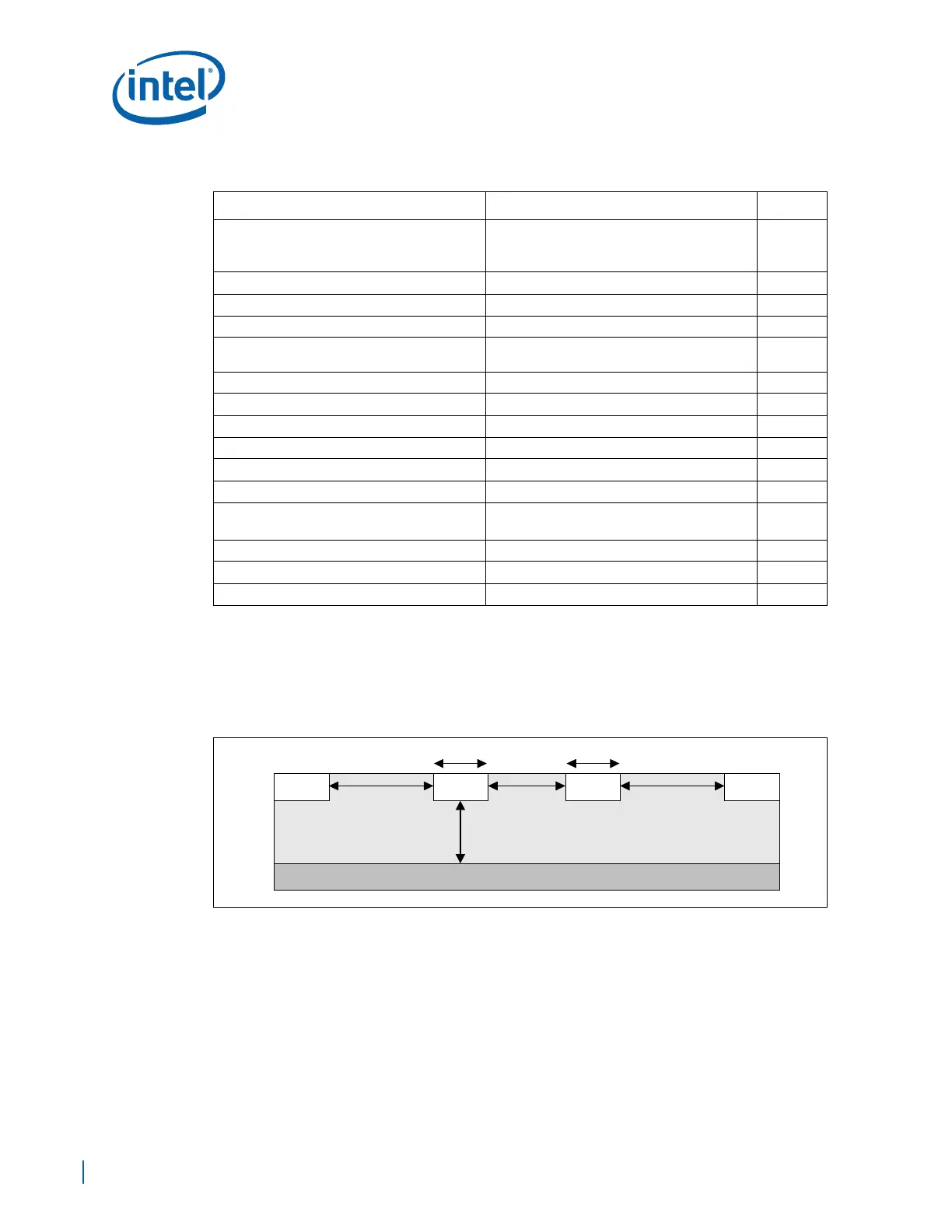
Figure 54. Trace Spacing for HOST_CLK Clocks
h
W
S1S1
HOST_
CLK
HOST_
CLK
Ground Plane
S
W