Intel
®
EP80579 Integrated Processor Product Line May 2010
Order Number: 320068-005US 331
System Memory Interface (SODIMM)—Intel
®
EP80579 Integrated Processor Product Line
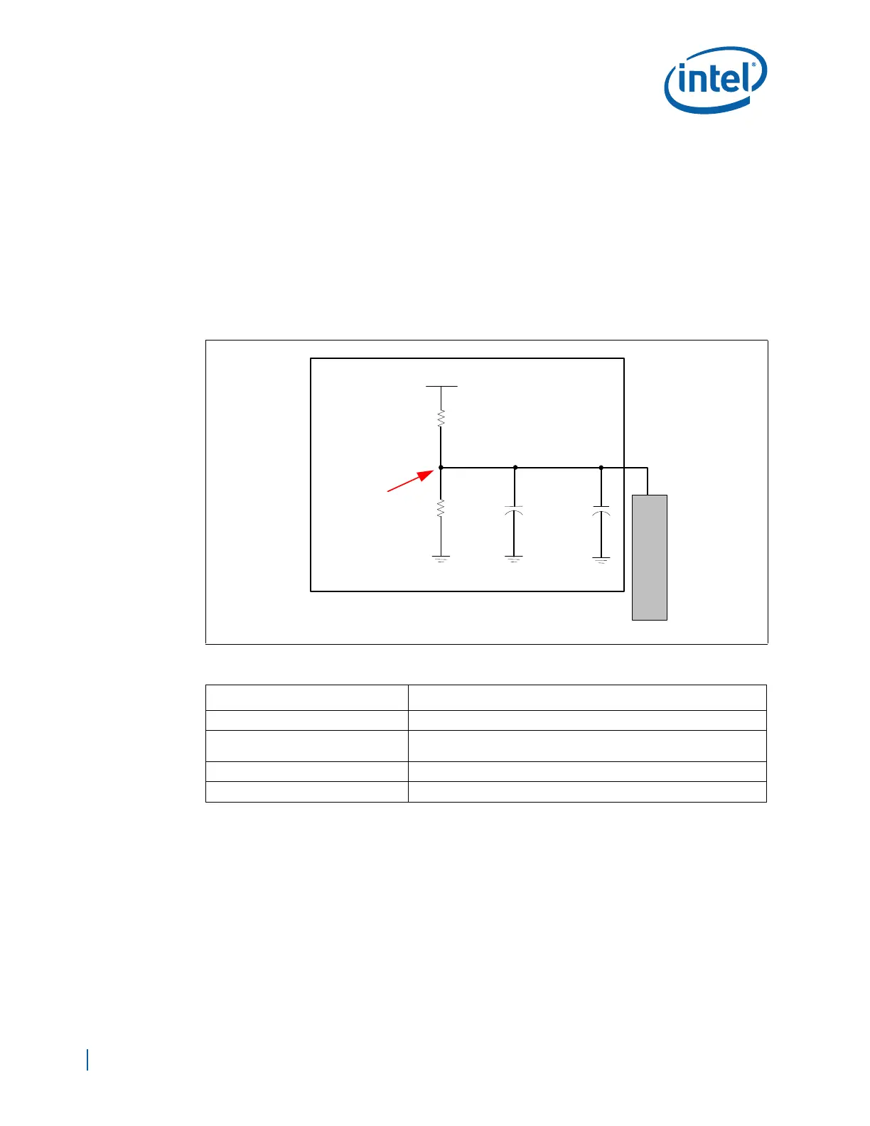
A.4.6.3 DDR2 Reference Voltage, DDR_VREF
The DDR2 system memory reference voltage (DDR_VREF) is used by the DDR2-SDRAM
devices to compare the input signal levels of the data, command, and control signals.
The DDR2-SDRAM DDR_VREF must be generated as shown in Figure A-8. Generate
DDR_VREF from a typical resistor divider using 0.1% tolerance resistors, with a 0.01 µF
cap tied to DDR_VREF. The DDR_VREF divider resistors must be placed as close to
possible to the SODIMM. The DDR_VREF must be decoupled locally at the SODIMM
connector. Finally, the DDR_VREF signal must be routed with as wide a trace as
possible. Table A-13 provides the routing and component guidelines for the Vref circuit.
Intel recommends at least a 20 mil wide trace with a minimum spacing of 12 mils from
other signals.
A.5 Decoupling Recommendations
When designing a board, the following decoupling recommendations should be
followed:
• Capacitors should be mounted as close to the EP80579 as possible. They should be
no further than 10mm from the edge of the EP80579 package for the DDR2
channel.
• Decoupling caps should be placed near any signal reference layer change.
This can
be done by adding a 0.1μF capacitor between DDR Power and Ground where the
Memory Clock traces change reference layers.
Figure A-8. DDR_VREF Generation Example Circuit
Table A-13. DDR V
REF
Generation Requirements
Parameter Guideline
Nominal Trace Width 20 mils
Voltage Divider
Place resistor divider consisting of two resistors as close as possible
to SODIMM.
Decoupling requirements 0.01 µF and 0.1µF capacitors
Decoupling placement Place decoupling caps as close as possible to SODIMM (Figure A-8)
S
O
D
I
M
M
V1P8_DDR
49.9 Ω,
0.1%
0.1 uF
0.01 uF
49.9
Ω,
0.1%
DDR_VREF
Voltage
Circuit