Intel
®
EP80579 Integrated Processor Product Line—System Memory Interface (DIMM)
Intel
®
EP80579 Integrated Processor Product Line
Platform Design Guide May 2010
133 Order Number: 320068-005US
9.7.3.3 DDR2 Reference Voltage, DDR_VREF
The DDR2 system memory reference voltage (DDR_VREF) is used by the DDR2-SDRAM
devices to compare the input signal levels of the data, command, and control signals.
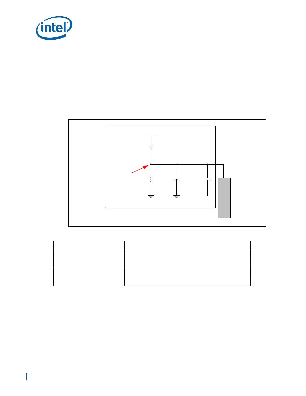
The DDR2-SDRAM DDR_VREF must be generated as shown in Figure 85. Generate
DDR_VREF from a typical resistor divider using 0.1% tolerance resistors, with a 0.01 µF
cap tied to DDR_VREF. The DDR_VREF divider resistors must be placed as close to
possible to the DIMMs. The DDR_VREF must be decoupled locally at each DIMM
connector. Finally, the DDR_VREF signal must be routed with as wide a trace as
possible. Table 47 provides the routing and component guidelines for the Vref circuit.
Intel recommends at least a 20 mil wide trace with a minimum spacing of 12 mils from
other signals. For the best signal integrity, minimize this length as much as possible.
Figure 85. DDR_VREF Generation Example Circuit
Table 47. DDR V
REF
Generation Requirements
Parameter Guideline
Nominal Trace Width 20 mils
Voltage Divider
Place resistor divider consisting of two resistors as close as possible
to DIMMs.
Decoupling requirements 0.01 µF and 0.1µF capacitors
Decoupling placement
Place one decoupling cap at each of the DIMM sockets and one
decoupling cap at the EP80579 (Figure 85)
D
I
M
M
V1P8_DDR
49.9 Ω,
0.1%
0.1 uF
0.01 uF
49.9 Ω,
0.1%
DDR_VREF
Voltage
Circuit