Intel
®
EP80579 Integrated Processor Product Line—Controller Area Network (CAN) Interface
Intel
®
EP80579 Integrated Processor Product Line
Platform Design Guide May 2010
236 Order Number: 320068-005US
CNTXD and CNRXD are used to transmit and receive signals, which are relatively low
speed, up to 1 MHz. The only signal that requires special attention is CNTXEN; this
signal requires a series damping resistor. It is required to control the rise or fall time
the differential pair in the CAN Driver. Use the table provided in the data sheet for the
CAN Driver to determine the value of resistor R1.
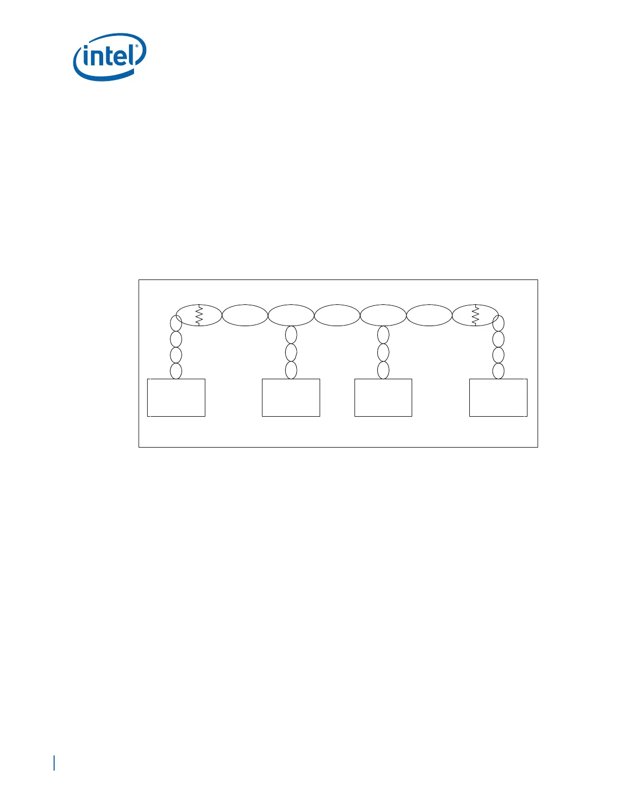
21.2 Multipoint Topology
CAN networks can implement multipoint topologies. The interconnect between nodes is
typically done with a simple twisted pair of 120 ohm impedance as shown in
Figure 145. The transmission line must be terminated at both ends of the line with a
120 ohm resistor. This is done to minimize reflections at the end of the line. The energy
sent by the transmitting node needs to be absorbed at the end of the transmission line
so that pulses are not reflected back and forth, and the energy is absorbed by the 120
ohm resistor.
Each of the messages sent by the transmitting node are received by every node in the
network, including the transmitting node. The transmitting node checks for errors or
collisions in the message send. If an error is sensed, the transmitting node will attempt
to retransmit. If two nodes attempt to transmit at the same time, the node sending the
highest priority message will win and the node sending the lower priority message will
stop transmitting immediately. All nodes on the network receive and process the
message send if it is identified to be for them. Multiple nodes can identify the message
to be for them, and process it at the same time. For example, in the case where there
are temperature sensors in the network and a broadcast message is sent to all devices
to read and send their respective temperature readings to the requesting node. Each
one of the temperature sensing devices will process the requesting message and start
sending their reading one by one.
21.2.1 Board Design Tips
• Implement standard board design routing rules for differential pairs signal.
• LVTTL signals can be routed to maintain impedance anywhere from 45 to 65 ohm.
• Follow design guides described by the PHY CAN transceiver used in your design.
Figure 145. CAN Multipoint Topology
BXXXX-001
NODE 2
CAN
CONTROLLER
NODE 1
CAN
CONTROLLER
NODE 3
CAN
CONTROLLER
NODE 4
CAN
CONTROLLER
Rt = 120 Rt = 120