Intel
®
EP80579 Integrated Processor Product Line—High-Speed Design Concerns
Intel
®
EP80579 Integrated Processor Product Line
Platform Design Guide May 2010
52 Order Number: 320068-005US
Differential clocking may also reduce the amount of noise coupled to other traces,
which improves signal quality and reduces EMI. I/O signals are particularly important,
because they often leave the system chassis (serial and parallel ports, keyboards,
mouse, etc.) and radiate noise that has been induced onto them. A single-ended clock's
return path is usually a reference plane, which is shared by other signals/traces. When
noise is created on a single-ended clock, the noise may appear on the reference plane
and may be coupled to I/O traces. A differential clock's return path is the clock-bar
signal/trace, which is more isolated than the reference plane and minimizes potential
I/O trace coupling.
For best results, the trace lengths and routing of the clock lines must be closely
matched, and spacing between the two traces must be kept as small as possible. This
minimizes loop area and maximizes H-field cancellation. In addition, the real and
parasitic terminations of each signal of a differential pair must be the same. Also, the
skew between the signal level transitions on the two lines must be small compared to
the rise time of the level transitions.
Placing ground traces on the outside of the differential pair may further reduce
emissions. Intermediate vias to ground may be needed to reduce the opportunity for
re-radiation from the ground traces themselves. Distance between vias must be less
than ¼ of a wavelength of the fifth harmonic of the processor core frequency.
5.6 Length Tuning
High-speed source synchronous interfaces have very small setup and hold windows. As
a result, the signals as a group are very sensitive to skew. A common way to reduce
skew is to tune all of the lengths such that the setup and hold windows have the same
positional relationship. Length tuning is the matching of two or more signals’ total flight
time, within a tolerance, to center the setup and hold windows.
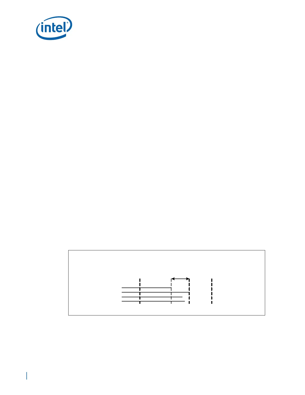
Length tuning has several key parameters: signal to be tuned, absolute minimum flight
time, absolute maximum flight time, and tolerance. The absolute minimum and
maximum flight times define the flexible solution space within which lengths may fall.
For a signal to be properly tuned, it must fall within that solution space and be within
the length tuning tolerance. Figure 25 shows the relationship of these parameters.
A tolerance is a value specifying how far off from exact is allowed. Typically, tolerance is
specified in a specific direction, such as –1 ps or ± 2 ps.
The minimum and maximum allowed flight times are at the end points of the tolerance
window. The tolerance window may fall anywhere within the range between absolute
minimum flight time and maximum flight time. The remainder of this section may refer
to ‘minimum allowed flight time’ as ‘minimum flight time’ and may refer to ‘maximum
allowed flight time’ as ‘maximum flight time’.
Figure 25. Length Tuning Parameters
absolute
minimum
flight time
absolute
maximum
flight time
tolerance
Signal flight time
Signals
minimum
allowed
flight time
maximum
allowed
flight time