Intel
®
EP80579 Integrated Processor Product Line May 2010
Order Number: 320068-005US 167
Universal Serial Bus (USB) Interface—Intel
®
EP80579 Integrated Processor Product Line
Length Tuning Requirements
Length matching over LT within a pair is 60 mils or less
Segment length matching, L1 to L1’, L2 to L2’, and L3
to L3’ is 20 mils or less
-
EP80579 Breakout
4 mils width with 4 mils spacing for maximum of
500 mils, minimize this length
-
Note:
1. Strictly observe the characteristic trace impedance. In this regard, requirements for the layers, trace
width, and trace spacing are secondary.
2. See Section 12.2.2.3 for more information on possible cable lengths for front panel headers.
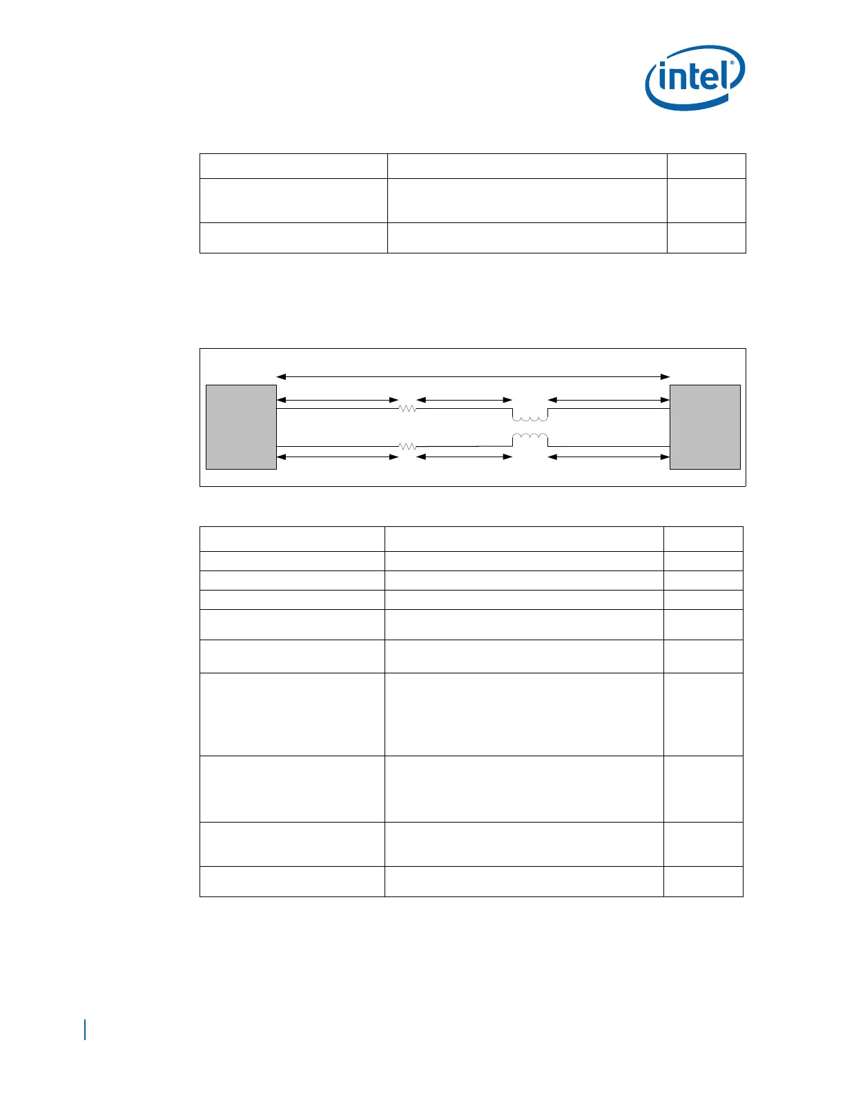
Figure 110. USB Trace Lengths For EP80579 Front Panel Solution
Table 62. Case 3, USB Routing Guidelines – Optional Front Panel Solution
Parameter Routing Guidelines Figure
Signal Group USBp[1:0], USBn[1:0] -
Reference Plane Ground Referenced, Stripline, or Microstrip -
Layer Assignment Layers 3 or 8 -
Characteristic Trace Impedance
(Zo)
1
90 Ω ±10% (differential) -
Nominal Trace Width
4.75 mils – microstrip
4.5 mils – stripline
Figure 112
Figure 113
Nominal Trace Spacing
Trace Spacing, edge-to-edge:
5.25 mils–microstrip
5.5 mils–stripline
Pair-to-pair spacing, edge to edge: 45 mils minimum
Spacing to clock signals: 45 mils minimum
Spacing to non-clock signals: 45 mils minimum
Figure 112
Figure 113
Nominal Trace Length
2
Keep all lengths as short as possible.
L1 to a header is dependent on the length of the cable
connecting the header to the front panel daughter
card. See Table 63 for detailed trace length
requirements.
Figure 111
Length Tuning Requirements
Length matching over LT within a pair is 60 mils or less
Segment length matching, L1 to L1’, L2 to L2’, and L3
to L3’ is 20 mils or less
-
EP80579 Breakout
4 mils width with 4 mils spacing for maximum of
500 mils, minimize this length
-
Note:
1. Strictly observe the characteristic trace impedance. In this regard, requirements for the layers, trace
width, and trace spacing are secondary.
2. See Section 12.2.2.3 for more information on possible cable lengths for front panel headers.
Table 61. Case 2, USB Routing Guidelines – EP80579 Front Panel Option (Sheet 2 of 2)
Parameter Routing Guidelines Figure
EP80579
USB
Connector
or
USB
Header
Choke
L2
L2'
L1'
L1
LT = L1 + L2 + L3
L3'
L3
0 ohm
0 ohm