Intel
®
EP80579 Integrated Processor Product Line—Local Expansion Bus (LEB) Interface
Intel
®
EP80579 Integrated Processor Product Line
Platform Design Guide May 2010
239 Order Number: 320068-005US
Table 88 contains information for trace length measurements that came from the
Development Board. Use this information as a reference when designing similar
topologies. It is strongly recommended to perform simulations for your specific
applications.
22.3.2 Chip Select Topologies
Chip Select is a point-to-point signal that must be closely routed to match the Address,
Data, and Control signal trace lengths. In order for signals to arrive at the same time
through the bus and avoid timing issues, all three groups must tightly match to
+/- 500 mil.
External board pull-ups are required on EX_CS_N to ensure the signal remains
deasserted, so that a spurious transfer does not start due to board noise. Additionally,
the system designer is responsible for ensuring that all the tri-stated signals do not
become indeterminate. It is recommended to terminate the EX_CS_N signal with a 10K
ohm pull-up resistor.
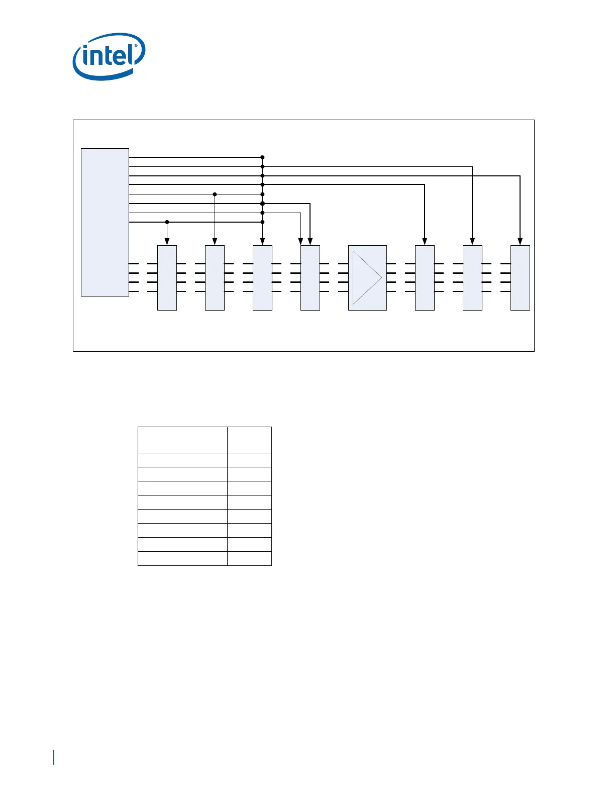
Figure 146. Multi-drop Topology Diagram
EP80579
BUFFER
EX_CS0#
L2L1 L3 L4 L5
L2L1 L3 L4 L5
L2L1 L3 L4 L5
L2L1 L3 L4 L5
EX_DATA
EX_ADDR
EX_RD#
EX_WR#
L6
L6
L6
L6
L7
L7
L7
L7
L8
L8
L8
EX_CS1#
EX_CS2#
EX_CS3#
EX_CS4#
EX_CS5#
EX_CS6#
EX_CS7#
L8
STRATA
FLASH #1
STRATA
FLASH #2
COMPACT
FLASH
MEZZ
#1
MEZZ
#3
MEZZ
#2
EX_CS[7:0]#
FPGA
Table 88. Multi-drop Topology Trace Lengths for the Development Board
Trace
Average
Length
L1 2.5 inch
L2 1.0 inch
L3 2.5 inch
L4 2.0 inch
L5 1.0 inch
L6 1.5 inch
L7 1.0 inch
L8 5.0inch