Intel
®
EP80579 Integrated Processor Product Line May 2010
Order Number: 320068-005US 75
System Power Delivery Guide—Intel
®
EP80579 Integrated Processor Product Line
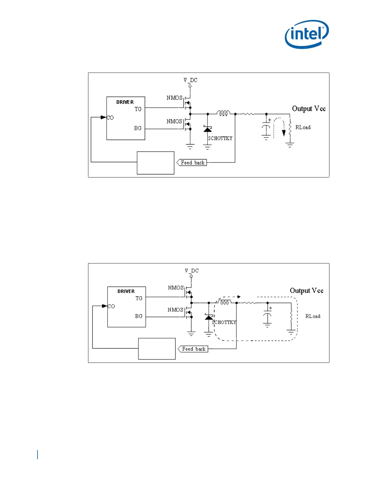
6.6.3.3 High Current Paths During Switching Dead Time
When the top MOSFET turns OFF and before the bottom MOSFET (there may be more
than one of these) is turned ON, the pattern of current flow changes. The inductor is no
longer being supplied current through the top MOSFET and starts to collapse its
magnetic field. The inductor literally becomes a generator at this point. The dashed line
in Figure 44 shows the current path during the time that both top and bottom MOSFETs
are OFF, also known as dead time. During dead time, there is a high current flow
through the inductor, processor, ground, and the Schottky diode. The diode and its
traces must be laid out in a way to minimize both stray inductance and resistance with
short, fat traces or planes.
6.6.3.4 High Current Path With Bottom MOSFET(s) Turned ON
A few nanoseconds after the top MOSFET is turned OFF, the bottom MOSFET(s) is
turned ON. The high current path now switches from the Schottky diode to the bottom
MOSFET(s), the current path shown by the dashed/arrow line in Figure 45. Minimize
stray inductance and resistance with short, fat traces or planes.
Figure 43. High Current Path During Abrupt Load Current Changes
Voltage
Regulator
Control Circuitry
Figure 44. High Current Path With Top and Bottom MOSFETs Turned Off (Dead Time)
Voltage
Regulator
Control Circuitry