Intel
®
EP80579 Integrated Processor Product Line May 2010
Order Number: 320068-005US 53
High-Speed Design Concerns—Intel
®
EP80579 Integrated Processor Product Line
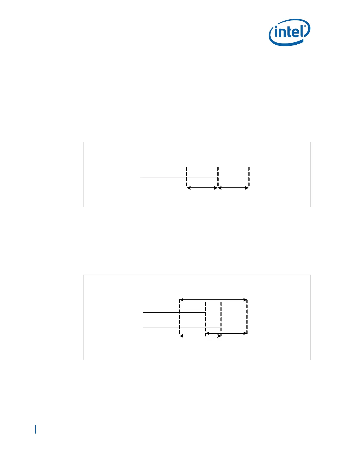
5.6.1 Signal-to-Strobe Flight Time Relationships
High-speed interfaces are commonly latched off a strobe or a clock. Length tuning
ensures that the required setup and hold times of the data signal to the strobe signal or
clock signal are not violated due to motherboard routing effects. As a result, each data
signal is length tuned with respect to the strobe signal or clock signal. This means that
the data signals are all within tolerance of the strobe signal:
Minimum_Signal
Flight Time
= Strobe
Flight Time
– Tolerance
Maximum_Signal
Flight Time
= Strobe
flight Time
+ Tolerance
Some groups of high-speed signals need to be length tuned to two strobes or clocks. In
this situation, all signals must be length matched to both strobes or clocks and the
strobes or clocks must be length matched to each other as well.
Minimum_Signal
Flight Time
= Longer_Strobe
Flight Time
– Tolerance
Maximum_Signal
Flight Time
= Shorter_Strobe
Flight Time
+ Tolerance
Figure 26. Signal Length Solution Space with One Strobe
Minimum_
Signal
Fl ight Tim e
StrobeFlight Time
– tolerance
Strobe
F light Ti me
Maximum_
Signal
Fl igh t Tim e
Str obe
Flight Time
+ tol erance
tol eranc e tol era nce
Figure 27. Signal Length Solution with Two Strobes
Minimum_
Signal
F light Time
Signal Length
Solution Space
tolerance
tolerance
Maximum_
Signal
F light Time
Longer_
Strobe
Fli ght Tim e
– To le r a nce
Shorter_
Strobe
Fli ght Tim e
+ Tolerance
Longer_Strobe
Fl ight Time
Shorter_Strobe
Fl i ght Time