Intel
®
EP80579 Integrated Processor Product Line—Universal Serial Bus (USB) Interface
Intel
®
EP80579 Integrated Processor Product Line
Platform Design Guide May 2010
168 Order Number: 320068-005US
12.2.2.1 USB 2.0 Trace Separation
Use the following separation guidelines (Figure 112 and Figure 113 show the
recommended trace spacing):
• Maintain parallelism between USB differential signals with the trace spacing needed
to achieve 90 Ω ±10%
differential impedance. Deviations will normally occur due to
package breakout and routing to connector pins. Ensure the amount and length of
the deviations are kept to the minimum possible.
• Use an impedance calculator to determine the trace width and spacing required for
the specific board stackup being used, keeping in mind that the target is a 90 Ω
±10%
differential impedance. The recommended board stackup parameters for
microstrip are 4.75 mil wide traces with 5.25 mil trace spacing, which results in
approximately 90 Ω ±10% differential trace impedance. The recommended board
stackup parameters for stripline are 4.5 mil wide traces with 5.5 mil trace spacing,
which results in approximately 90 Ω ±10% differential trace impedance. See
Figure 112 and Figure 113.
• Minimize the length of high-speed clock and periodic signal traces that run parallel
to the high-speed USB signal lines to minimize crosstalk. The minimum
recommended spacing to any clock signal is 0.050 inch.
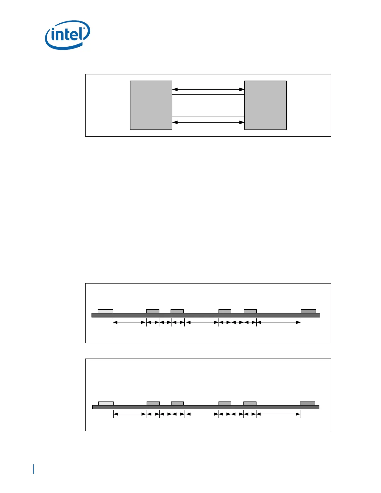
Figure 111. USB Trace Lengths For Optional Front Panel Option
Figure 112. (Microstrip) Recommended USB Trace Spacing
Figure 113. (Stripline) Recommended USB Trace Spacing
USBP0 USBP1USBN0 USBN1
45 45
5.25
4.75
5.25
45
Distance in Mils
Clock/High-
Speed
Periodic Signal
Low-speed
Non-Periodic
Signal
Differential Pair Differential Pair
4.75 4.75 4.75
45 454.55.54.5 4.5 5.5 4.5 45
Distance in Mils
Layers 3 and 8
Clock/High-
Speed
Periodic Signal
Low-speed
Non-Periodic
Signal
Differential Pair Differential Pair
USBP0 USBP1USBN0 USBN1