Intel
®
EP80579 Integrated Processor Product Line May 2010
Order Number: 320068-005US 179
System Management Bus (SMBus) Interface—Intel
®
EP80579 Integrated Processor Product
Line
• Amount of current available in the suspend power well (i.e., minimizing the load of
the suspend power well)
13.1.2 General Design Considerations
The following are general design considerations:
• The pull-up resistor size for the SMBus data (SMBDATA) and clock (SMBCLK)
signals is dependent on the bus load, which includes leakage currents for all
devices. Generally the SMBus device that can sink the least amount of current is
the limiting agent on how small the resistor can be. The pull-up resistor cannot be
made so large that the bus time constant ( ) does not meet the
SMBus rise and time specification.
• The maximum bus capacitance that a physical segment can reach is 400 pF.
• SMBus devices that can operate in STR (Suspend-to-RAM) must be powered by the
suspend power well.
• SMBus address contention as a design consideration.
•I
2
C devices should be powered by the appropriate core power well voltage. During
an I
2
C transaction, in which the device is sending information to EP80579, the
device may not release the SMBus if EP80579 receives an asynchronous reset. By
using the core power, the BIOS is able to reset the device if necessary. SMBus 2.0-
compliant devices have a time-out capability that makes them insusceptible to this
I
2
C issue, allowing flexibility in choosing a voltage supply.
• If SMBus is connected to PCI Express, it must be connected to all PCI Express slots.
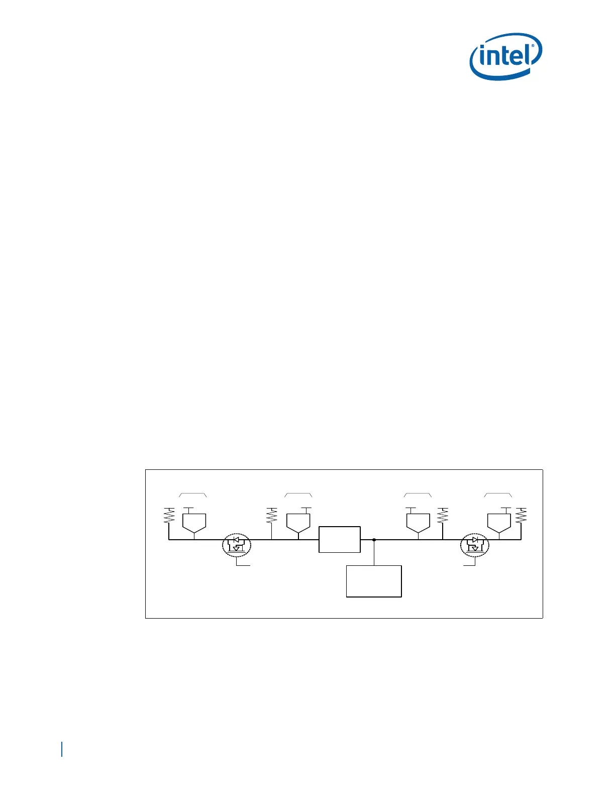
13.1.3 High Power/Low Power Mixed Architecture
This design allows for current isolation of high and low current devices while also
allowing SMBus devices to communicate while in S3. Leakage in the suspend power
well is minimized by keeping non-essential devices connected to the core power well.
This is accomplished by the use of a FET to isolate the devices powered by the core and
suspend power wells. See Figure 120.
Additional considerations for mixed architecture are shown below:
• The bus bridge must be powered by a voltage from the suspend power well.
• Devices that are powered by the suspend power well must not drive into other
devices that are powered off. This is accomplished with the “bus switch.”
• The bus bridge can be a device similar to the Phillips* PCA9515, used on the
Development Board.
Figure 120. High Power/Low Power Mixed Suspend/Core Power Well Architecture
B6391-01
Bus
Bridge
Vcc
Non-Standby
Devices
VccSusVCCPSUS VccSus VCCPSUS Vcc Vcc
EP80579
Buffered Power
Good Signal From
Power Supply
SMBus
Buffered Power
Good Signal From
Power Supply
SMBusSMBus
High
Current
Low
Current
Devices running
in Standby
Devices running
in Standby
Non-Standby
Devices
Vcc

 Loading...


