Intel
®
EP80579 Integrated Processor Product Line May 2010
Order Number: 320068-005US 98
Platform System Clock—Intel
®
EP80579 Integrated Processor Product Line
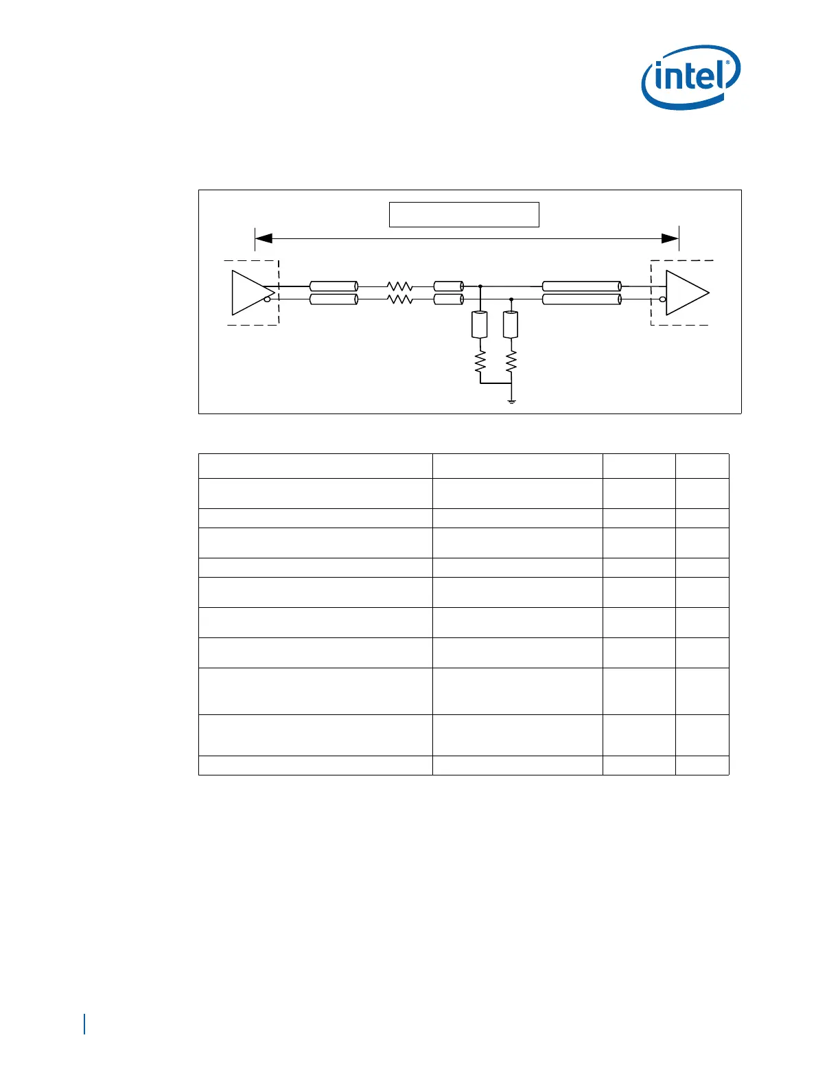
8.2.2.4 Source Clock to PCI Express* Components or Connectors
Figure 56. CLK100 Clock Group (SRC Clock) Topology
Table 20. 100 MHz SRC/SRC# Clock Routing Guidelines for PCI Express Slot/Component
Parameter Routing Guidelines Figure Notes
Trace Width – W
1
microstrip: 4.5 mils
stripline: 4.75 mils
Figure 57
1
SRC to SRC# spacing – S
1
10 mils Figure 57 2,3
SRC to Signal Spacing – S1
(includes spacing between SRC pairs)
20 mils Figure 57
Baseboard Impedance – Differential 100 Ω ±10% 2,3
Clock Routing Length
(L1, L1’): Clock Driver to Rs
0.5 in max Figure 56
4
Clock Routing Length
(L2, L2’): Rs to Rs-Rt Node
0.1 in max Figure 56
4
Clock Routing Length
(L3, L3’): Rs-Rt Node to Rt
0.1 in max Figure 56
4
Routing Length
(L4, L4’): Any Clock driver
(CK410/DB800) to component
Min: 3 in
Max: 20 in
Figure 56
5
Routing Length
(L4,L4’): Any Clock Driver (CK410/DB800) to
PCI Express connector
Min: 3 in
Max: 16 in
Figure 56
5
CLKN – CLKP Length Matching within 5 mils
L1'
L1
Rs
L2
L2'
L3
L3'
L4
L4'
Clock Driver
CK410, DB800
PCI Express*
Slot/Component
Rs
Rt Rt
LT = L1 + L2 + L4