Intel
®
EP80579 Integrated Processor Product Line—Universal Serial Bus (USB) Interface
Intel
®
EP80579 Integrated Processor Product Line
Platform Design Guide May 2010
176 Order Number: 320068-005US
12.7.2.2 Routing Considerations
Keep the following routing considerations in mind:
• Traces or surface shapes from Vcc to the thermistor, to C
BYPASS
, and to the
connector power and ground pins must be at least 50 mils wide to ensure adequate
current carrying capability.
• Power and ground nets must have double vias.
• Trace lengths must be kept as short as possible.
12.7.3 Front Panel Daughter Card
The best way to provide front or side panel support for USB is to use a daughter card
and cable assembly. This allows the placement of the EMI/ESD suppression
components right at the USB connector where they will be the most effective.
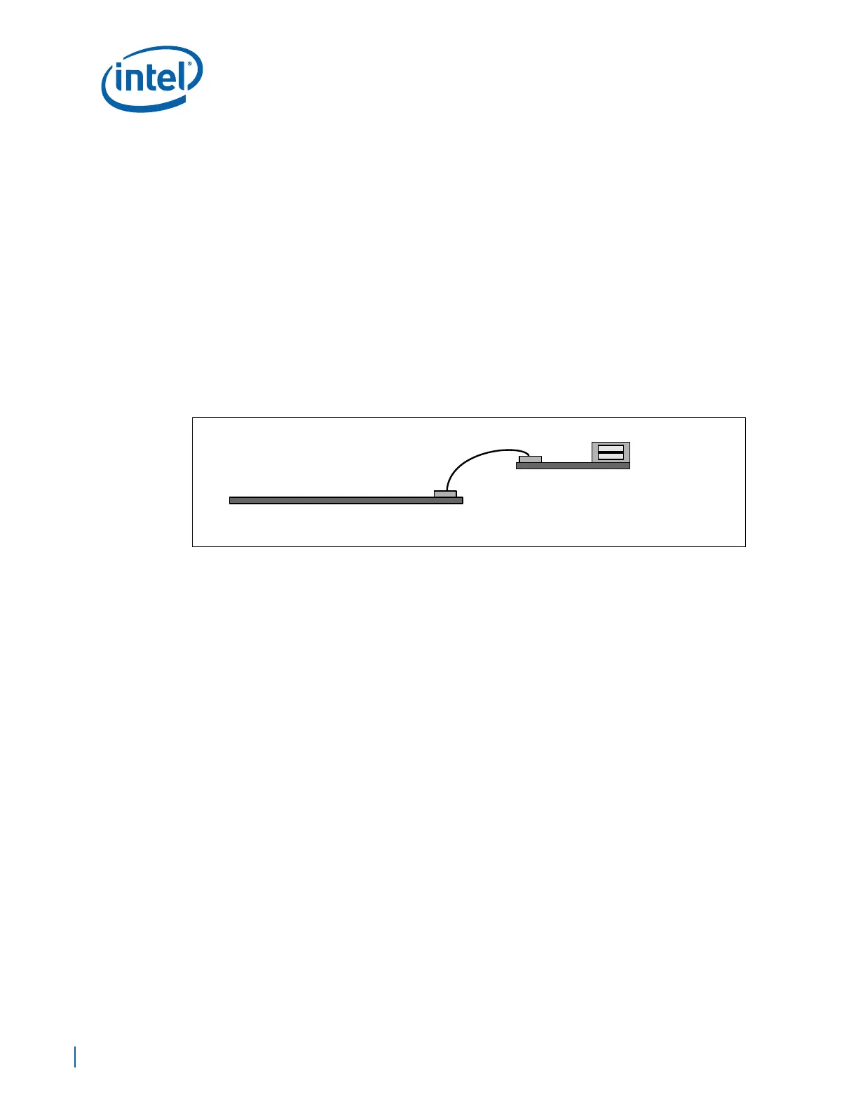
Figure 118 shows the major components associated with a typical front/side panel USB
solution that uses a front panel connector card.
When designing the motherboard with front/side panel support, the system integrator
must know which type of cable assembly will be used. If the system integrator plans to
use a connector card, ensure there are not duplicate EMI/ESD/thermistor components
placed on the motherboard, as this will usually cause drop/droop and signal quality
degradation or failure.
12.7.3.1 Front Panel Daughter Card Design Guidelines
Keep the following front panel daughter card design guidelines in mind:
• Place the Vbus bypass capacitance, CMC, and ESD suppression components on the
daughter card as close as possible to the connector pins.
• Follow the same layout, routing, and impedance control guidelines as specified for
motherboards.
• Minimize the trace length on the front panel connector card. Less than a 2 inch
trace length is recommended.
• Use the same mating connector pin-out as outlined for the motherboard in Section
12.7.2, “Motherboard/PCB Mating Connector” on page 174.
• Use the same routing guidelines as described in Section 12.2, “Layout Guidelines”
on page 164.
• Follow trace length guidelines given in Table 63.
12.8 Terminating Unused USB Interface
If the USB interface is not used, the termination is recommended to the interface.
Figure 118. Motherboard Front Panel USB Support
Motherboard
Front Panel USB Ports